Changeover point
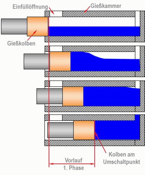
The point at die casting at which the plunger is accelerated from slow shot velocity v1 (velocity of the 1st phase) to high velocity v2 (mold filling velocity, velocity of the 2nd phase) (see fig. 1).In cold chamber as well as hot chamber machines, the metal in the shot sleeve (cold chamber die casting machines) or casting basin (hot chamber machines) has to be accumulated first on startup of the plunger. This accumulation of the metal (the 1st phase or forward phase) is carried out at low plunger velocities to
- displace the enclosed air during accumulation of the metal and
- to prevent air swirling with the casting metal.
However, the mold cavity has to be filled quickly at high velocities to
- achieve complete filling of the mold,
- prevent premature partly solidification,
- achieve a high casting quality and contour reproduction.
The required mold filling times for die casting may be very short so that high flow and plunger velocities are required in the mold filling phase (2nd phase). For this reason, die casting requires at least a two-phase control for the casting drive.
In summary, the following can be noted:
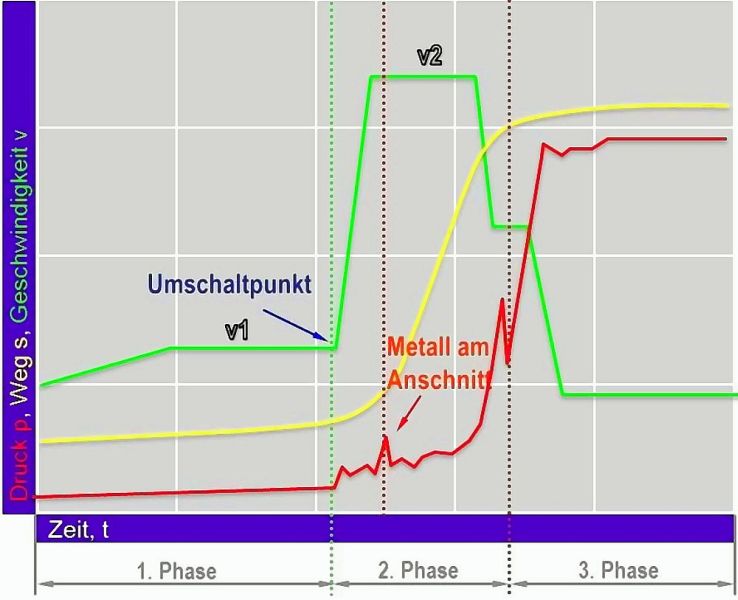
In the first phase, the casting metal is accumulated to the changeover point at low velocity. On reaching the changeover point, the plunger is accelerated to the velocity required for mold filling. The high velocity range is referred to as 2nd phase or mold filling phase. In this phase, the actual mold cavity is filled with the liquid metal (fig. 2). A two-phase control includes the slow shot phase and quick mold filling (with changeover from v1 to v2 at the changeover point) and with subsequent influence of the resulting end pressure (only the available accumulator pressure acts for final compression of the casting, see Casting pressure) on the filled mold cavity.
A three-phase control includes an intensifier at the end of mold filling (see the range of the 3rd phase in fig. 1) to increase the available end pressure for final compression over the accumulator pressure. The velocity control, however, is two-phase in both cases (slow shot phase and quick mold filling).Generally, the changeover takes place over the path, i.e. by entering the path point on programming of the casting curve (for electronic path measurement) or mechanically by actuation of a control cam running on the plunger rod. In both cases, a control pulse opens the shot valve at the pressure accumulator or activates the proportional valve and releases the “shot” (video 1). Video 1: Injection process with changeover to the 2nd phase at the changeover point, with the kind permission of Les Fondeurs de France
Depending on the required conditions of the respective casting, the changeover point can be adjusted and is a significant quality criterion that is to be monitored.
The correct position of the changeover point
Particularly for horizontal cold chamber machines, the changeover point has to be first coordinated with the filling level as the shot sleeve is only partly filled before startup.
The lower the filling level the more air has to be discharged via the joints and mold parting plane during the slow shot phase. For this reason, it is generally useful to aim for a maximum initial filling level that cannot always be achieved in practice. Depending on the machine model and shape (construction height of the fixed plate, casting stroke, mold height, sprue pin, required clearances for metal feed etc.), restrictions in length of the shot sleeve occur. In practice, high initial filling levels cannot always be achieved by shortening the shot sleeve and/or by using a smaller plunger diameter. This kind of measures may not always be useful.
In general, the possibility of using a higher dosing exists. However, it also results in thicker casting residues with subsequent reduction of the cycle time (longer casting residuecooling time) or unnecessarily high thermal stress (see Thermal balance) and increases the costs of the casting as the material costs increase.
Generally, a defined air volume is enclosed when the plunger passes over the filling opening of the shot sleeve. Due to complete accumulation of the casting metal in the shot sleeve, the air – if possible, without swirling – is guided in front of the metal and respectively discharged. Fig. 2 illustrates this state and Video 2 illustrates a proper slow shot phase on a water model. Video 2: Accumulation of the metal in the slow shot phase, video of the water model with the kind permission of Bühler AG
At this time, it is usually changed over to the high plunger speed and the liquid metal is then accelerated in the runner and pressed into the mold cavity at the gate with the now selected and correct gate speed (see Flow speed during die casting). It has to be considered here that the air volume that is partly also present in the runner is swirled with the metal which may have a negative impact on the casting quality (see Video 3). Video 3: Swirling and enclosed air in the runner after initiation of the 2nd phase at the changeover point, video of the water model with the kind permission of Bühler AG
One method to prevent air swirling in the runner and to define the changeover point is to calculate the path point at which the metal is accumulated directly up to the gate. Due to dosing fluctuations at standard dosing furnaces or dosing devices, the exact path point is difficult to determine in practice. A possible remedy for this is the use of metal front contact sensors which are directly installed in the runner in front of the gate to ensure exact changeover independent of dosing fluctuations, if they are coupled with the control of the machine.
Often, however, multiple gates are available that are not always installed at the same height. Respectively, the best changeover point to ensure the casting quality is to be defined by non-destructive testing. Due to inertia, the acceleration the driven mass - melt, plunger, plunger rod, etc. - cannot be directly applied by the casting drive and requires time. For this reason, it may be favorable to select the changeover point shortly after the metal accumulation, i.e. shortly after reaching a filling level of 100 %. At this time, the flow peak should not yet have reached the mold cavity.
In initial approximations, the path point at accumulation of 100 % filling level in the shot sleeve is a suitable selection for the changeover point. The path point is calculated according to Eq. 1:
Eq. 1: 
| sFilling level100% | Path point of the plunger in mm at accumulation to 100 % filling level = initial approximation to determine the position of the changeover point | |
| lKG | Active shot sleeve length in mm | |
| mCasting | Total casting weight in g | |
| ρl | Density of the casting metal in g/cm3 in liquid state (l=liquid) | |
| AK | Plunger surface in cm2, calculated from AK = dK2*π/4, where dK is to be assigned the plunger diameter in cm |
For thick-walled and high-volume parts, priming at slow velocities may also support the casting quality, i.e. the changeover point is already set when the mold cavity is partly filled. This process is very common as it reduces the required final compression volume. In any case, interpretation of the results of a mold filling simulation (see Solidification simulation) is recommended as it returns the conditions at time of changeover very accurate and realistic.
Summary:
The changeover point defines the duration of the 1st phase. On changeover, all moveable parts have to be accelerated. This requires a defined stroke as well as time and force. For this reason, the changeover point lies within the range of the runner filling. Correct changeover requires high dosing accuracy!
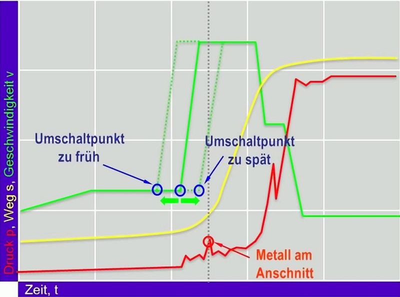
Too late changeover point (fig. 3):
The melt partly fills the mold cavity with the velocity of the 1st phase. There is a risk of cold flow and the mold filling time is extended. The melt that is already in the mold is no longer properly accelerated and
the filling changes.
Too early changeover point (fig. 3):
A roll over wave may occur in the shot sleeve and there is a risk of increased air pockets.