Counterpressure casting process
Special construction and further development of the low pressure gravity die casting process In the counterpressure casting process, not only the furnace but also the die are subjected to pressurized gas (usually with compressed air).
Principle
The actual casting process is carried out in a similar way to low pressure casting, also with the help of a riser tube. The casting metal is conveyed up into the die by the riser tube. However, the pressurization of the metal bath in the furnace in order to convey the melt up into the die is caused by a pressure difference Δp by lowering the gas pressure in the pressurized die a little. The causes an overpressure in the furnace which causes the metal to rise into the die.
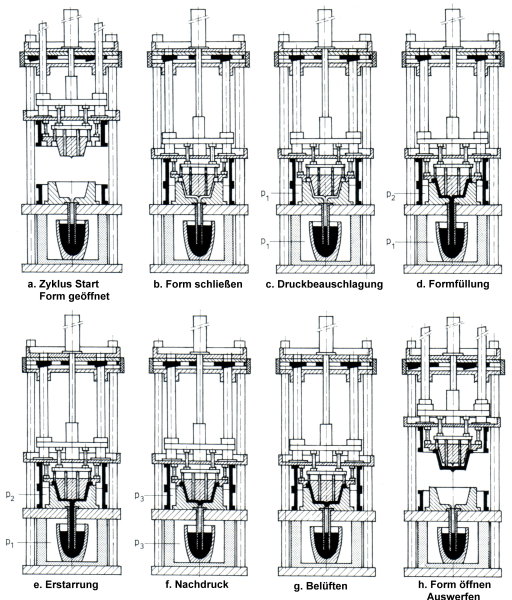
Figure 1 shows the casting cycle in a counterpressure die casting machine: First the die is closed (Figure 1b) and then both the furnace chamber which contains the crucible with the liquid metal and the die chamber above it with vertically parted die are subjected to pressurized gas at the same time; the same pressure p1 is the present in both chambers (Figure 1c). Now the pneumatic connections between both chambers are closed and, through aeration which can be regulated, the pressure in the die chamber is reduced to p2. Due to the pressure difference Δp = p1 – p2 which is created in this way, the liquid metal rises into the mold cavity (Figure 1d); this is the actual casting or mold-filling process.
The pressure and the counterpressure are maintained until th end of the solidification, whereby the casting solidifies under the influence of the pressure difference Δp in the die (Figure 1e). After solidification is complete, the two chambers are connected again pneumatically and the pressures balance out to the equilibrium pressure p3. The remaining liquid metal sinks back down in the riser tube and flows back into the crucible (Figure 1f). The pressure p3 is then maintained for a short time and acts as final pressure on the casting. By aerating both chambers, the pressurization is finally removed completely (Figure 1g). The machine then opens the die and the ejector mechanism withdraws the casting (Figure 1h).
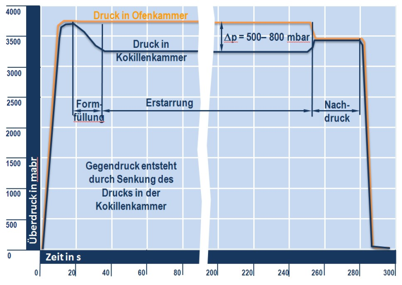
Figure 2 shows the schematic pressure pattern during a a machine cycle. The counterpressure allows the regulation of the filling speed of the metal into the mold, independently from the pressure on the molten bath in the furnace. Here, the creation of the pressure difference Δp proceeds entirely linearly, unlike in the low pressure casting process. The main area of application is light metal die casting, e.g. for the car industry (in particular for wheel rims and wheels). Here, the counterpressure is set at around 4-6 bar and the pressure reduction Δp is usually 0.5 - 0.8 bar. In aluminum casting, compressed air is usually used as pressurized gas, less frequently inert gases are used (then mainly N2 and Ar).
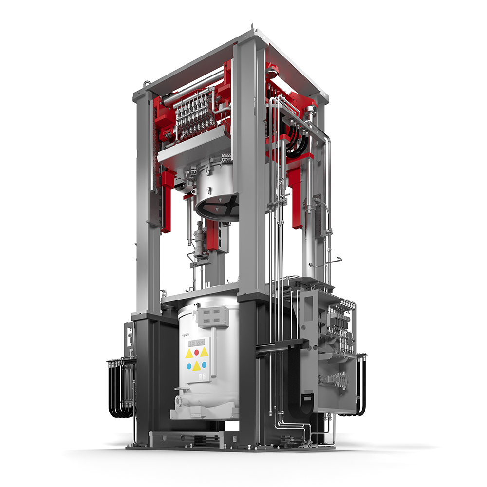
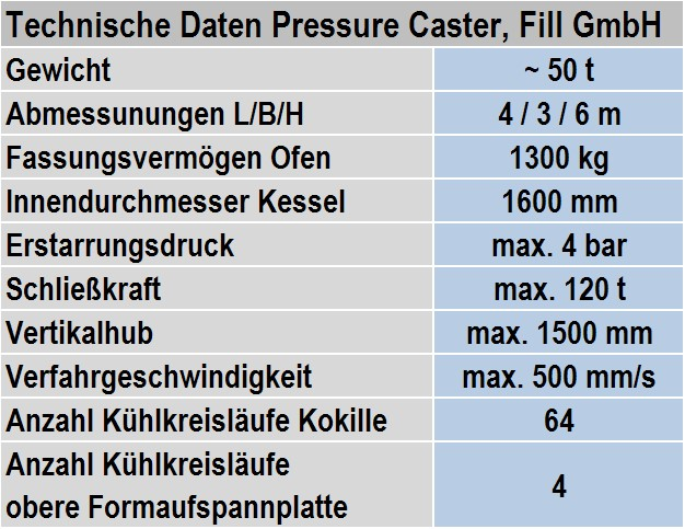
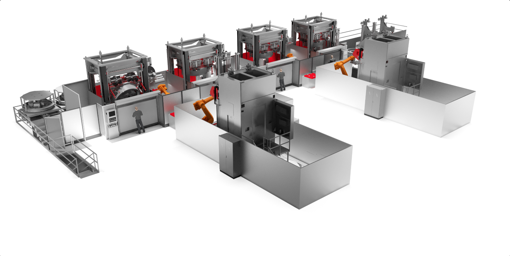
Figure 3 (Fill GmbH) shows a counterpressure casting machine and its technical data is given in Table 1 (Fill GmbH). In addition to the high quality, high degree of automation and an optimized cycle time, the counterpressure process, in comparison to conventional die casting, achieves considerably better material utilization. Figure 4 shows chained counterpressure casting machine (Fill GmbH).
Movies 1 - 3 (Fill GmbH) shows the tilting of upper tool plate, change furnace as well change tool.
A variation of the counterpressure casting process is the Precocast process (q. v.), in which higher pressures are used.