Die casting mold
Metallic permanent mold for the production of die castings using a die casting machine.
The die casting mold contains the mold cavity, i.e. the space which forms the contours and dimensions of the casting. The liquid die casting alloy is fed in via channels which is called the gating system.
A die casting mold is essentially made of two parts and consists of the fixed (stationary) and the movable (ejector) mold halves. The stationary die half is mounted on the die casting machine’s fixed fixing plate; the ejector die half is fixed to the movable fixing plate and contains the casting ejector. When ready for casting, the two mold halves are closed and are kept closed on the machine by the die locking force. The contact surface between the two mold halves is called the mold parting or mold parting plane. The opening and closing movements are only applied to the ejector die half. Cavities or undercuts are demolded by mechanically or hydraulically operated core slides (cores).
Fig. 1 shows the schematic construction of a die casting mold. The stationary die half (2) consists essentially of two mold elements: the stationary pattern plate (5) and a mounting plate (3). The ejector die half (moving die half) (1) always also contains the ejector. For this, there is a suitable mold holder on the back of the ejector die half which consists of a mounting plate (3) with spacers (7). This means that there is enough space to insert the ejector plate (8) with the ejector pins fitted in it. The assembly plate is screwed to the ejector die half through the spacers using tie rods.
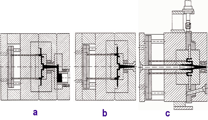
Fig.2 shows a cross section of a die casting tool for a cold chamber die casting machine with a horizontal shot sleeve. The names of the tool parts of die casting tools are standardized in DIN 16750:1991. The requirements for the metal mold for the production of non-ferrous alloys according to the die casting, low pressure die casting and gravity die casting process are determined in EN 12891. Fig. 3 shows, from left to right, a die casting tool for a horizontal cold chamber machine in 3-plate construction (a), a tool for a hot chamber die casting machine (b) and a mold with core slides for a cold chamber machine with vertical shot sleeve (c).
The quality of the design of a die casting mold largely determines the properties of the casting and the economic efficiency. When designing and producing a die casting mold, the following should be considered:
- Dimensioning of the die casting mold
- Selection of mold steels (s. Hot-forming steel) and their heat treatments
- Design of the thermal fluid die heating and cooling
- Design and calculation of the casting system and the (forced) ventilation
- Ease of maintenance
- Production which is adapted to service life
- Number of mold cavities
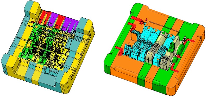
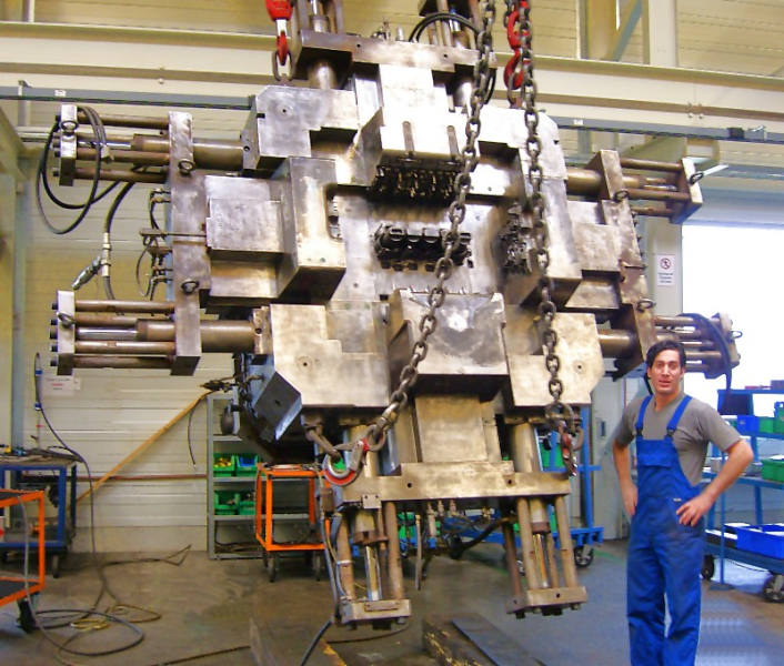
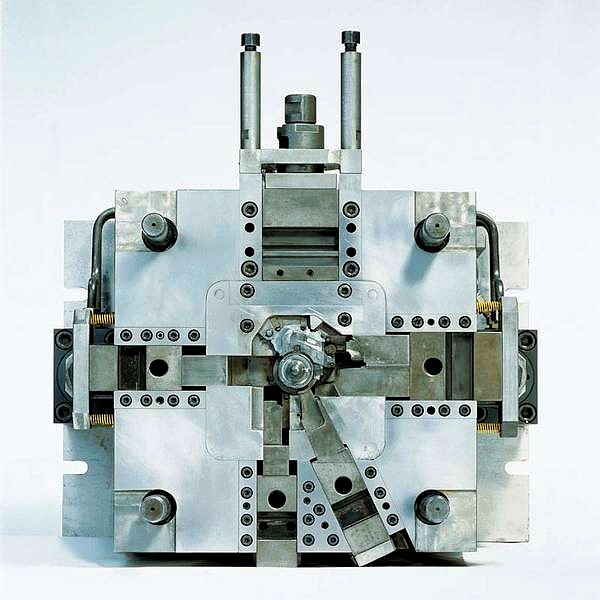
Designs of mold inserts and the moving die half for a series 4-cylinder crankcase are shown in Fig. 4 (Schaufler Tooling GmbH). Fig. 5 (Schaufler Tooling GmbH) shows the 3D construction of a large mold for a series 5-cylinder engine block, the dimensions of such a large form can be taken from Fig. 6. (Schaufler Tooling GmbH) Finally, Fig. 7 shows a precision tool for a zinc die casting.
Literature references:
DIN 16750:1991, Press-, Spritzgieß- und Druckgießwerkzeuge, Benennungen und Symbole, DIN Deutsches Institut für Normung e.V.
Druckguss aus NE-Metallen, Technische Richtlinien, Verband Deutscher Druckgießereien (VDD), 2008.
Brunhuber, Ernst: Praxis der Druckgussfertigung, Fachverlag Schiele & Schön, Berlin 1960.