Favorable casting design
In an ideal situation, the process-specific advantages of casting ought to be taken into account prior to final determination of the component geometry. Consequently, the following aspects must be clarified and complied with among the customers and the foundryman:
- 1. Economic efficiency
- 2. Optimized functional and strain-related design
- 3. Optimized engineering with regard to casting processes and material properties
- 4. Optimized model-related and structural features
- 5. Surfaces optimized with regard to cleaning and machining (machining allowances must be reduced to a minimum)
- 6. Design allowing for ease of testing
- 7. Esthetic apprearance
The volume contraction occurring during solidification (s. Solidification shrinkage, Shrinkage) and any resulting feeding deficiency can be largely compensated through directed solidification. To this end, the following prerequisites must be generally met:
- If possible, prevent accumulation of material.
- Junctions in cross sections must be eliminated as far as possible.
- Wall thicknesses must be increased towards the risers (s. a. Heuvers circle method)
- Avoid abrupt changes in wall thickness
- Gradation of cross sections must be precisely determined using the modulus calculation method (s. Modulus, Casting modulus).
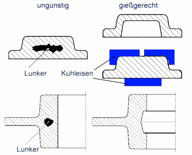
Avoidance of material accumulation
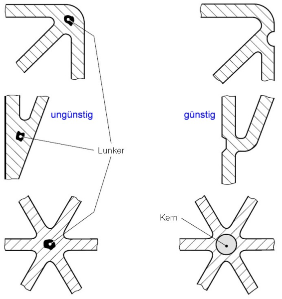
Due to varying cooling rates, the molten material will solidify slower in zones with material accumulation than in the zones with thinner walls in the ambience. Caused by volume contraction during transition of the material from liquid to solid state, hollow spaces, also referred to as shrinkagecavities are formed in these “hot spots”. Risers or cores will make the casting more expensive.
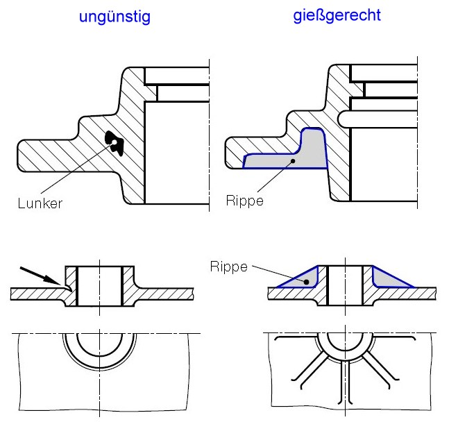
Simple constructional changes, help to avoid these “hot spots” in the moste cases (Fig. 1). Implementation of notches and/or ribbing prevents material accumulation in many situations. Moreover, ribs are capable of inhibiting the risk of cracking (Fig. 2).
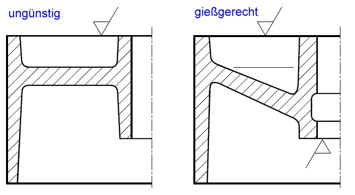
Avoidance of bubble formation
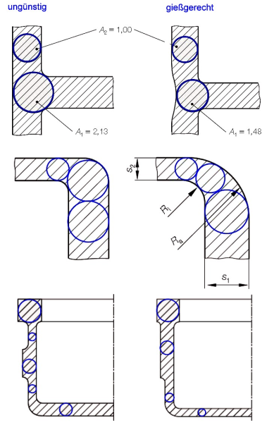
To prevent undesired bubble formation and, in the consequence, unsightly casting surfaces, disc surfaces ought to be given an inclined layout (Fig. 3).Correct structural design of change in wall thickness
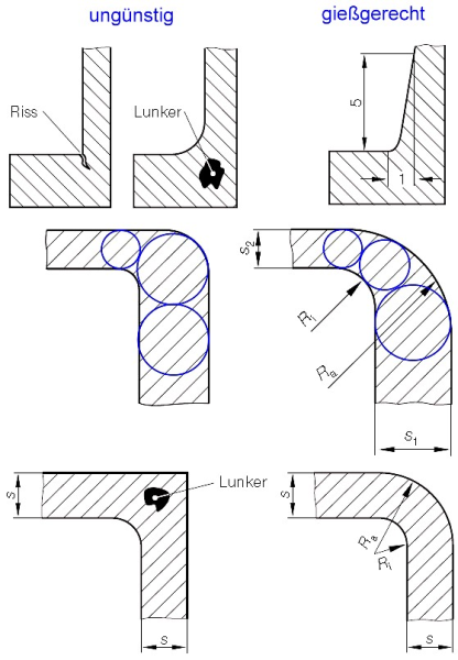
In zones with transitions from thin to thicker walls, there is a risk of cavities and even cracking in case that fillets and radii are dimensioned too small. In such cases, smooth transitions with a gradient of 1:5 must be implemented (Fig. 4, top row). For rounded transitions between varying wall thicknesses, the following rules must be applied for the radii (Fig. 4, middle row):

and

For transitions between equal or similar wall thicknesses and radii (Fig. 4, bottom row) the structures must be designed as follows:

and

Favorable design of junctions
Junctions, in which ribs or walls meet, cause accumulation of material. These must be eliminated by special designs, i.e. by insertion of cores or through special feeder structurs. Otherwise, there is a risk of cavity formation.
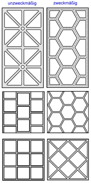
Avoidance of distortion through shrinkage stresses
Star-shaped ribbing (Fig. 6, left) is unyielding so that during cooling of the casting no shrinkage clearance is available. This results in significant stresses for the material and the risk or distortion or cracks. Comb-shaped ribbing (Fig. 6, right) only has little restricting effects on shrinking of the cast part within the mold so that only minor internal stresses occur in the casting during cooling. Consequently, the risk of cracks and distortion is prevented while simultaneously achieving great component strength.
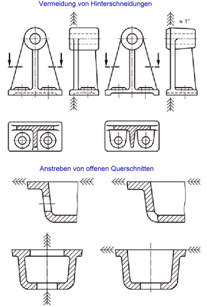
Avoidance of offset and formation of burrs
The parting plane (s. Mold joint) of a sand mold or an ingot must be designed as simply as possible. The parting line at the castings should run straight and not pass through surfaces whose appearance might be impairedd through grinding of the mold parting burrs. The layout of the parting planes must be such that those surfaces that are intended to be unmachined and for which absolute dimensional accuracy is required, are not separated by the mold joints. This also helps prevent potential offsets. If the mold joint is inappropriately positioned, deburring is made difficult and costs are increased. Consequently, under ideal conditions, the parting planes must be positioned such that the workpiece can be easily deburred (Fig. 7).
Implementation of mold inclinations
After determining the mold parting plane, it must be ensured that the outer surfaces are inclined in stripping direction. Otherwise the models cannot be removed without damaging the mold. According to DIN EN 12890, the mold inclinations (α) must be specified in the drawings in degrees of the angle. With lack of inside inclinations, internal cores are required.
Avoidance of back drafts and cores
Transverse ribbing and eyes must also be designed so that the models can be easily stripped from the mold (avoid back drafts and undercuts because they require attachments or loose pieces). Cores are expensive and encumber molding. They should be avoided if possible. It is better to aim at open profiles and cross sections. Requried openings must therefore be designed so that there is no need to use cores.
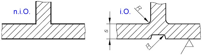
Avoidance of sharp edges and abrupt transitions
Sharp edges must be prevented in any case since, on the one hand the are difficult to implement by foundry engineering and, on the other hand, the easily cause cracking. The rounding radius R ought to be around a third to a quarter of the wall thickness value s. Surfaces that are only intended for machining, form sharp edges with the raw casting wall.
Correct design of ribbing and rib connections
To ensure reduction of casting stresses, ribbing must always be designed thinner than the actual wall thickness of a part. Rib thickness should be 0.8-fold the wall thickness (Fig. 11, top row). For double-sided ribbing, the individual ribs must be offset to reduce material accumulation and thus prevent formation of cavities. In case of bracing used in cast foundations as is illustrated in Fig. 11, bottom row, it becomes clear in what way material accumulation can be avoided by separating two rib connection points and narrowing of the rib in the corner of the housing.
Application of the Heuvers circle method
A simple tool for control of material caccumulation is the application of Heuvers circle method. In a favorably engineered casting, the ratio between adjacent inscribed circle diameters (A1/A2) must be almost one, respectively, (Fig. 12). To ensure dense feeding of materials with rather high solidification contraction rates (e.g. cast steel GS or Cu), the wall thicknesses must be designed particularly carefully. Application of the Heuvers control circles is also recommended for such situations. Favorable casting engineering requires for the circle areas to become bigger towards the riser (directed solidification).
Additional references:
Design of castings
Favorable casting engineering
Strain-related design
Heuvers circle method
Literature references:
Technische Richtlinien, Sand- und Kokillenguss aus Aluminium, Bundesverband der deutschen Gießerei-Industrie
Alfred Herbert Fritz, Günter Schulze (Hrsg.), Fertigungstechnik, 8., revised edition, 2008 Springer-Verlag Berlin Heidelberg