Firing cracks
In literature, firing cracks are often also referred to as heat cracks, temperature cracks, irregular cracks, heat shock cracks, thermal fatigue cracks or firing cracks network and are the most common cause of failure of die casting molds.
Firing cracks occur as a result of high thermal load cycling in the die casting mold (thermal cycling cracking).
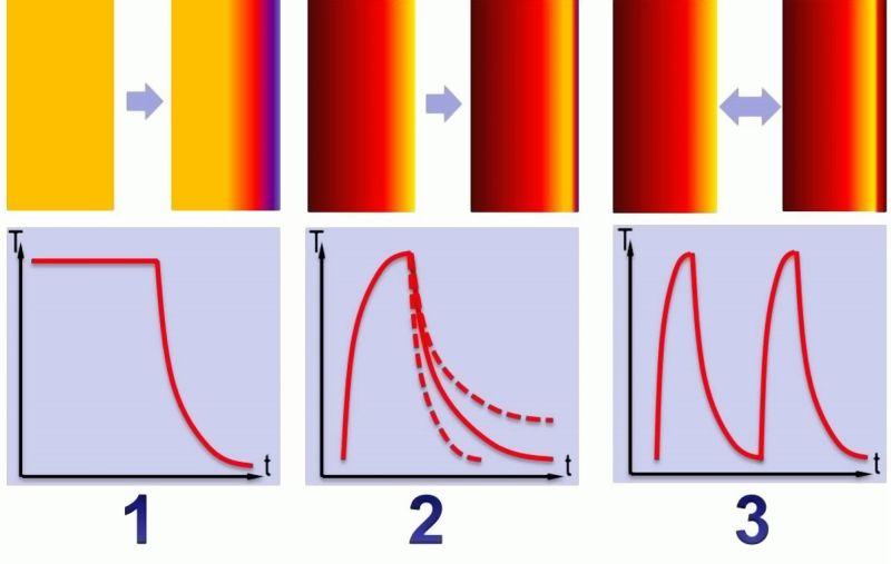
In general, the following three types of thermal load cycling are distinguished:
Abrupt and strong cooling of a slowly, i.e. unevenly heated mold contour or mold wall (Fig. 1-1).
Abrupt and one-sided heating of a cold or only slightly heated mold contour or mold wall and its cooling at any speed (Fig. 1-2).
The sequence of short, abrupt temperature changes at a thick-walled workpiece (Fig. 1-3).
The damaging mechanisms in the phases of crack formation and growth can be described as follows.
At materials with a positive thermal expansion coefficient, these also include hot-forming steel, heating leads to an expansion of the material. If the mold is heated from the surface, the limited heat conductivity of the material leads to a greater or lesser temperature gradient. If it is assumed that there is no load or internal stress in unaffected state, internal compression stress occurs in the heated ranges and internal tensile stress in the ranges that are not yet heated due to the mechanical correlation between the ranges with different temperatures.
In the beginning of the heating process, the affected surface range is still low in comparison to the overall cross section of the mold. However, as a force balance is required in the entire workpiece, this leads to considerably higher internal compressive stress in the surface range than internal tensile stress in the residual component. If these internal compressive stresses exceed the yield point, these surface ranges are plastically deformed (compressed) by stress relief to the limit of elasticity. If this temperature and stress is held over a longer period of time, creeping may occur in the material for further stress relief and the plastic deformation may be increased.
While plastic deformation is an irreversible process, the stresses are reversed by cooling the surface. This way, the narrow, compressed surface range is highly deformed by tensile stress and the interior is slightly deformed by compressive stress.
Plastic deformation also causes hardening of the respective surface range. This way, the remaining internal tensile stress in this surface range at the end of the next temperature cycle will be slightly higher than after the first temperature cycle. With an increasing number of cycles, the tensile stresses are increasing up to a plateau value.
Further temperature load cycling then takes place under constant influence of this tensile stress plateau value and respectively leads to fatigue cracks that can be identified at their crack surface structure.
The stress that is decreasing towards the interior of the tool, delay the crackgrowth with increasing penetration depth. For this reason, the cracks are not longer growing at a certain depth.
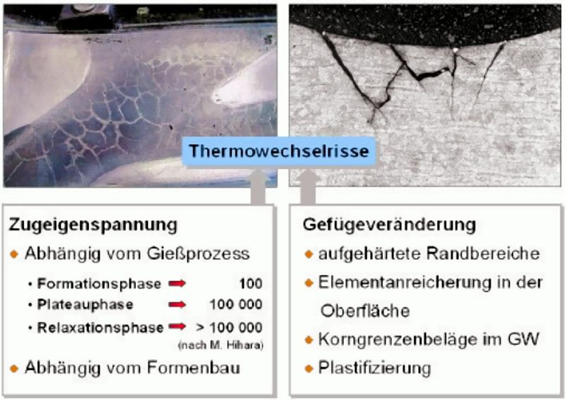
Thermal load cycling in die casting processes also lead to massive structural changes at the edge of the mold. This also includes carbide formation (see Carbide) at the grain boundaries that lead to embrittlement and increasing plastification of the material.
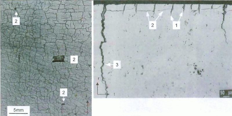
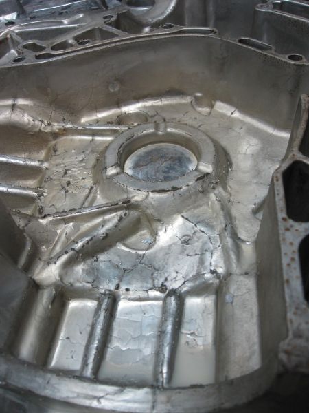
Firing cracks mainly occur at even surfaces where no macroscopic concentration of stress occurs. They may range from a fraction of a millimeter to far into the depth of the workpiece and their width ranges from the microscopic range to several millimeters (Fig. 2).On the development of internal stress during the life cycle of a die casting mold, M. Hihara carried out examinations that distinguish the following three different phases (see also Fig. 3).
Formation phase: up to approx. 100 temperature cycles, the internal stress is increasing and develop from internal compressive to internal tensile stress by means of thermal load cycling.
Plateau phase: up to approx. 100,000 cycles, the internal stress remains constant and crackgrowth continuous.
Relaxation phase: after approx. 100,000 cycles, the internal tensile stresses completely disappear as the internal stress is relieved by the continuing growth of cracks.
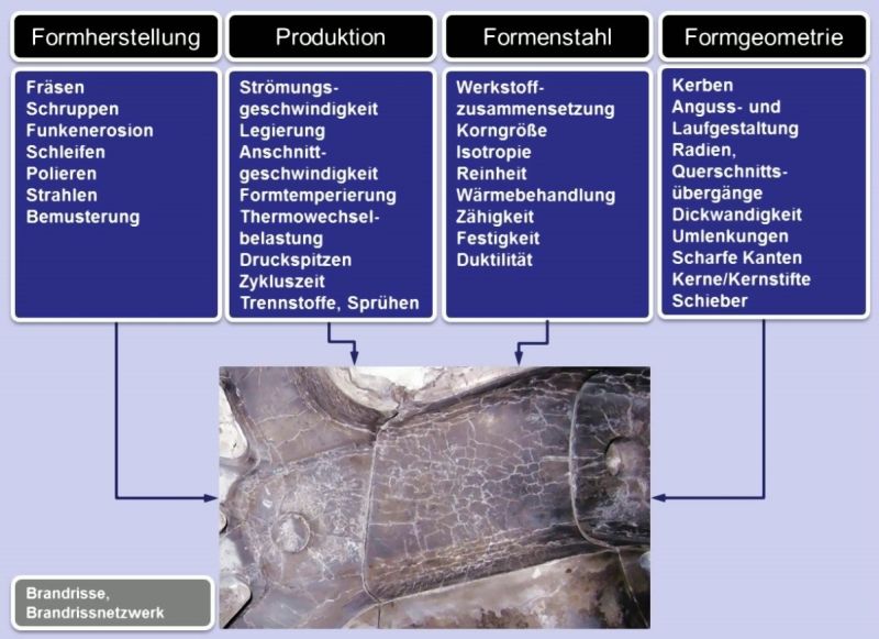
This appearance is generally known. Less known is the fact, that massive internal tensile stress occurs already during production of the mold considerably impairing the service life.Thermal cycling cracks are influenced by numerous factors that are summarized in
the following overview in Fig. 4.
The material itself and particularly its crack toughness and strength at increased temperatures have a decisive influence on the service life of the molds. This also includes the isotropy and purity of the mold steel and its heat treatment which have to ensure an uniform initial structure.
During the production of die casting molds and subsequent sampling, considerable internal tensile stresses are applied to the component surface.
Mold geometry, sprue and runner design or small radii define the point of cracking.
The production sequence considerably defines the service life. Particularly, the following influences are to be mentioned: Flow rate during die casting, type of casting alloys (see Die casting alloy, Ductile aluminum alloys), gate speed, mold temperature and mold temperature control, cycle times and separating agents. All these influences are interacting and generally define thermal load cycling.
In conclusion, the following can be noted on the formation of firing cracks:
On contact with the melt, stress occurs on the tool surface due to thermal expansion. The maximum stress may exceed the heat yield point, the stress is relieved by plastic flow. After ejection, the temperature gradient is reversed - the crack formation at the surface is initiated. The mesh width of the network of cracks marks the temperature gradient and is closely connected with the mechanical properties of the tool steel.
Firing cracks are clearly visible at the die cast part and lead to an increased level of rework by blasting or grinding. Examples for castings with signs of fire cracking are illustrated in the figures 5 and 6.Apart from the reduction of thermal load cycling and the temperature gradient in the surface range of the die casting mold, the requirements for high service lives also include the application of hot-forming steels with high purity and toughtness.
Additional references:
Chipping
Mold erosion
Stress cracks
Literature references:
Siefer, W.: On firing cracks, Gießerei 55 (1968) no. 24, S. 737-742.
Hihara, M.; Mukyama, Y.: Behaviour of Thermal Fatigue on Hot Die Steel Samples Treated by Gas-Nitriding, Int. J. Japan Soc. Prec. Eng., Vol. 26, No. 2 (June 1992), page 120-122.
Eliasson, L.; Sandberg, O.: Impact of various parameters on the thermal load cycling resistance of hot-forming steels for die casting molds, Gießerei-Praxis no. 9/10, 1990, page 154-160.
Klobcar, D., Tusek J., Taljat, B.: Thermal fatigue of materials for die casting tooling, Materials Science and Engineering A, 2007.
Wallace, J. F., Schwam, D.: Die Cast. Eng. (2000) 50-58.
Berns, H.: Example for damage at hot-forming tools, Druckgusspraxis 2/2005, page 65-72.