Gravity die casting process
In gravity die casting, melts are cast up or down into permanent molds under the influence of gravity or low pressures. Depending on the procedure, a distinction is made between
- Gravity die casting process (Gauss Automazione srl.)
- Tilting gravity die casting process
- Low pressure gravity die casting process (Gauss Automazione srl.)
- Counterpressure casting process
- Special casting processes and variations of the gravity die casting process, e.g. Precocast process, squeeze casting, pressure die casting process
The main areas of application are in light metal die casting (aluminum die casting alloys and magnesium alloys) and heavy metal die casting (mainly brass); cast iron is also cast in dies.Under consideration of the tools costs, a wide range of series sizes can be covered.
Filling and solidification
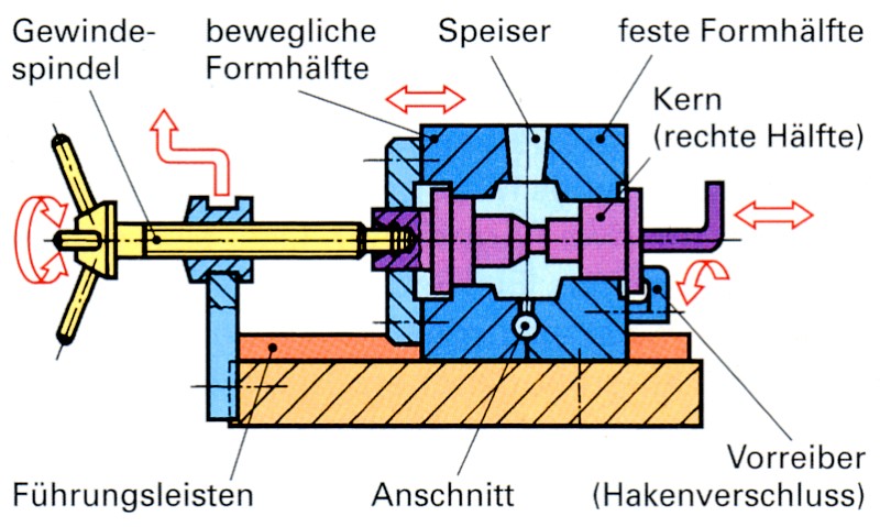
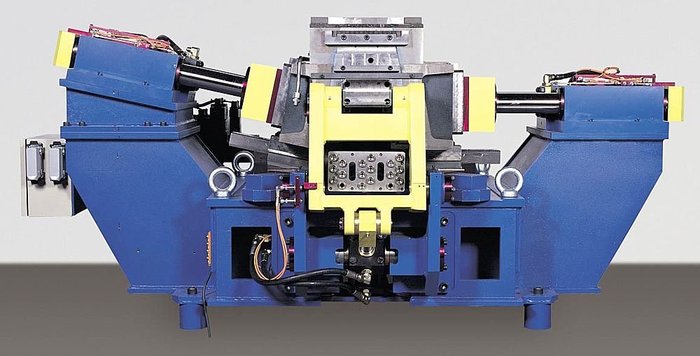
Simple dies can be filled by hand; a die with mechanical moving parts is shown in Figure 1. For large series, die casting machines (Figure 2) or mechanical or automatic die casting plants are used. The individual stages of the work such as putting in the core, closing the mold, opening the mold, ejection and extraction of the casting, blowing out and coating can then be carried out automatically.
Die casting differs from sand casting mainly in the fact that the metal mold material with its - in comparison to mold sand - high thermal conductivity causes an accelerated cooling of the solidifying melt. As a consequence of this rapid solidification, a comparatively fine-grained and dense structure forms. Better mechanical properties and a high impermeability of the casting are associated with this. The higher reproducibility of the creation of a dense structure has also lead to the fact that gas-tight and liquid-tight fittings, mostly made of brass and with medium-sized dimensions, tend to be made using the die casting process and not using sand casting.
Further advantages of die casting as opposed to sand casting are:
- better precision and higher dimensional accuracy,
- a better surface quality and exact rendition of contours due to the metal permanent mold,
- the elimination of sand conditioning,
- a high output for simple parts,
- a shorter production time and cycle time due to rapid solidification,
- the possibility of installing an automated sequence.
Light metal gravity die casting
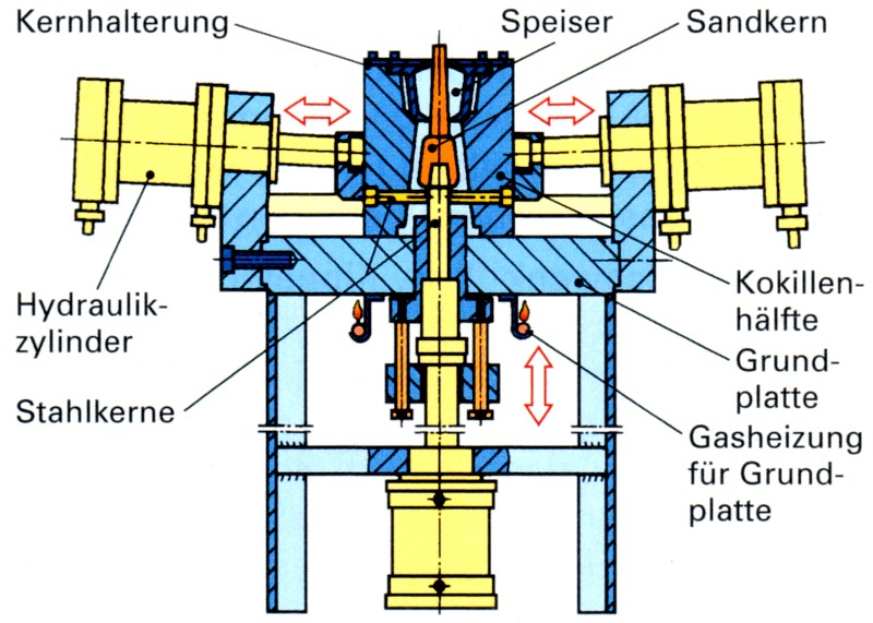
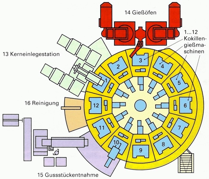
A distinction is made between dies with vertical and horizontal main parting planes and also, according to type, between full molds, mixed molds (with sand cores) or half molds (with one sand and one die half).Vertically parted molds can be operated by hand and placed on a table for casting. Both mold halves are fitted with guide dowels or guide pins so that they fit exactly when opened and closed; larger dies are moved on an additional guide rail which is embedded in the casting table.Dies with horizontal main parting planes consist of a horizontal base plate, on which two or more core slides slide, which often surround a vertical metal core which is taken out from above. Additional cores can also be built into the core slides and into the base plate (Figure 3). For larger quantities and in order to shorten the cycles time, casting carousels are also used (Figure 4).
The following are used as die materials:
- Structural steels
- Flake graphite cast iron
- Hot working steels (similar to pressure casting molds made of 1.2343 or 1.2344, for higher quantities)
- Special molybdenum alloys or tungsten heavy metals for highly stressed mold components
Light metal casting materials which are suitable for die casting are standardized (s. Aluminum gravity die casting alloys). As with sand castings, die castings can also be heat treated in any way, are suitable for welding and can undergo decorative anodic oxidation if a suitable alloy is chosen.
Before casting, the die must be coated perfectly and heated, usually with a gas burner. The coating lasts for several casting cycles and must therefore only be improved or replaced when necessary. A suitably heated die usually does not need to be heated any more during the casting operation: the heat transfer which takes place in each casting process is sufficient to maintain the mold temperature needed for casting. However, for more complex castings, additional heating but also mold cooling are definitely necessary.
In the standard gravity die casting process, the mold is filled using gravity and usually using bottom pouring (s. a. Casting method), i.e. the melt is filled through a downsprue, then flows over a runner which is below and possibly to the side of the actual casting, via the gate(s) into the mold cavity. This means that the mold is filled from the bottom to the top. The following factors influence the mold filling time:
- the feed rate of the alloy
- the gate area
- the geometry
- the thermal conductivity of the alloy and the die
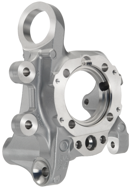
Figure 5 shows an example of a casting for a chassis which must meet demanding requirements for the mechanical characteristic values and the casting quality.
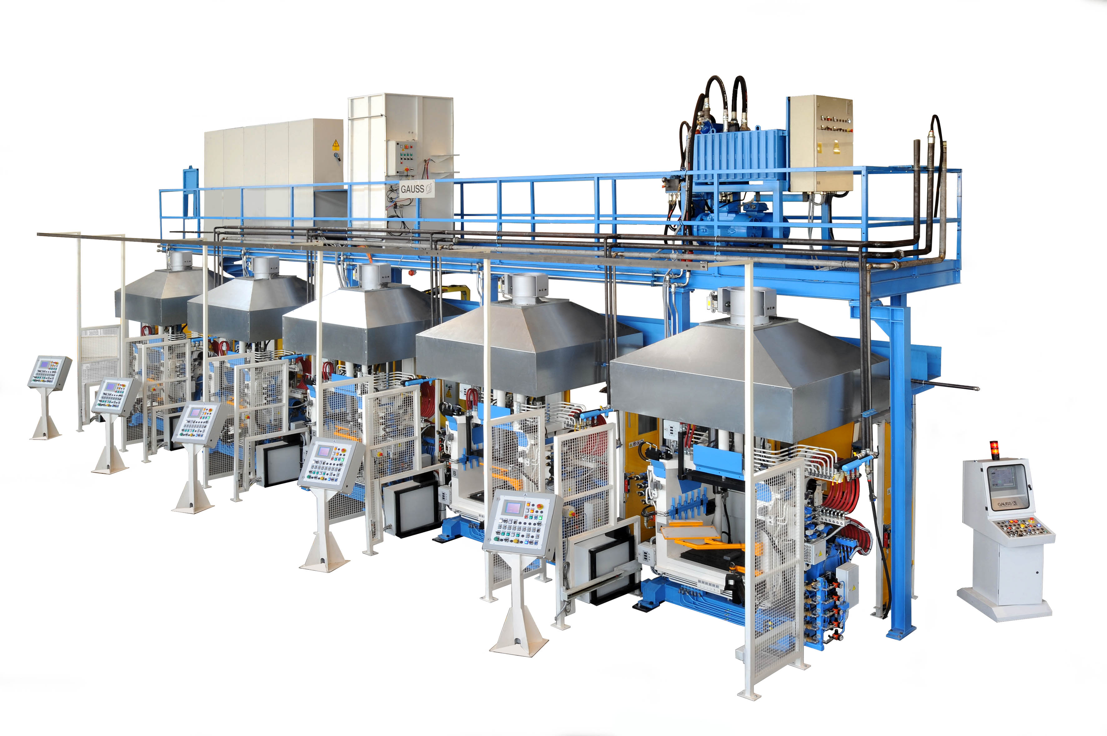
Figure 6 shows an example of an gravity die casting plant (Gauss Automazione srl.)
Literatur references:
Anwendungstechnologie Aluminium, Friedrich Ostermann, Springer Verlag, Berlin, 1998.
Handbuch der gießereitechnischen Berufe, Verlag Europa-Lehrmittel, Nourney, 2004.
Handbuch der Fertigungstechnik, Band Urformen.