Impact test
Material test according to DIN EN 10045 to determine the toughness of a material specimen under a sudden impact and the existing notch effect. This test method is used for all metal materials and is one of the most commonly used mechanical material tests in addition to the hardness test and tensile strength test (see Tensile test).
The specimen, also called impact specimen, of the material to be examined is notched on one side (V- or K-notch) and is tested in the cooled or heated state.
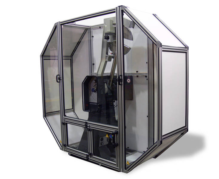
In the test, a pendulum impact tester (Fig. 1) is used to strike the unnotched back of the specimen with a pendulum hammer at a certain kinetic energy which results in the deformation or destruction of the specimen. Notching the specimen greatly intensifies the test conditions due to the increase in stresses within the notch base. The sharper the notch, the larger the increase in stresses. The deformation is concentrated in the small area inside the notch base. The impact work values determined for different specimen shapes deviate from each other. Therefore, the specimen shape must be indicated in any case.
One fraction of the kinetic energy applied by the pendulum hammer is consumed when the specimen is crushed or deformed. The energy consumption varies depending on material and temperature, causing the pendulum hammer to swing upwards at the other side. If the material is tough, it swings less high than with brittle material. The toughness measure used for the material or material state to be tested is the work needed to break the impact specimen. Therefore, according to eq. 1, the impact work to be determined is
Eq. 1: 
W = impact work in Joule
m = pendulum hammer mass in kg
g = gravitational acceleration (9.81 m/s2)
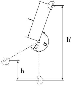
h’- h = swinging height of the pendulum hammer (Fig. 2)
The value used for quantifying toughness is usually the energy absorption or deformation until fracture. In addition, the so-called transition temperature is used for identifying toughness. This is the temperature at which transition from tough to brittle behavior occurs.
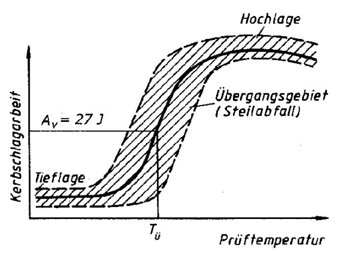
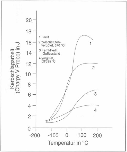
The test method is especially suitable for testing the material behavior depending on temperature, thus determining the transition from tough (ductile) to brittle behavior as a function of temperature. The work values established at different temperatures for the same material are entered into a DBTT diagram based on the temperature (Fig. 3).Face-centered cubic materials (austenitic steels, nickel, copper, aluminum) are tough even at low temperatures: they only break upon previous plastic deformation (Fig. 3, upper shelf).
Cast iron or hardened steels exhibit a brittle material behavior over the entire temperature range; they break with a brittle fracture (Fig. 3, lower shelf).
Body-centered cubic materials (all non- and low-alloy steels, chrome, molybdenum) and partly materials with a hexagonal lattice exhibit good toughness with only low spread at high temperatures (upper shelf, ductile fracture). At low temperatures, they are brittle and show no significant spread (lower shelf, brittle fracture). Between the lower and upper shelf, there is a steep transition with heavily spread work values, as shown in Fig. 3.
The position of the steep transition section is marked by the transition temperature TT. Due to the large spread range in the steep transition section, there is no generally valid definition of the transition temperature.
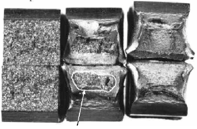
The fracture faces shown in Fig. 4 represent the three different types of fractures
in impact specimens made of the same material but impacted at different temperatures.As an example, ductile, highly tough nodular graphite cast iron shows a pronounced upper shelf/transition/lower shelf behavior, the characteristic S curve representing the transition from ductile to brittle. The transition temperature is dependent on the chemical composition, in particular on the silicon and phosphorus content. It rises with increasing silicon content (Fig. 5), increasing phosphorus content and increasing pearlite content.
The embrittling effect of phosphorus in the nodular graphite cast iron is the cause for the negative influence this element has on impact strength. For nodular graphite cast iron with low-temperature toughness, it is therefore necessary to not only adjust the silicon content but also the phosphorus content to <0.1%.
The transition temperature of ferritic nodular graphite cast iron rises proportionally with an increase in 0.2% yield strength. A comparison of various impact strength-temperature curves of ductile cast iron grades is summarized in Fig. 6.
Additional references:
S. Hasse, Duktiles Gusseisen, Handbuch für Gusserzeuger und Gussverwender, Schiele und Schön, Berlin 1996;
DIN EN 10045