Induction crucible furnace
In addition to the cupola furnace, the induction crucible furnace is the most important melting unit for the foundry.
The following principle works:
An AC current flows through a coil, creating a magnetic field. This penetrates the conductive insert material inside the coil and generates eddy currents according to Joule's law. These eddy currents then cause the feed material to heat up.
If enough energy is supplied, the feed material melts.
Since the magnetic flux generated by the coil current runs both through the melt, but largely through the crucible wall between the coil and the melt, heating of the entire furnace structure and an impermissibly high magnetic stray field outside the furnace must be avoided. This is done by the outer laminated cores, which prevent magnetic inference.
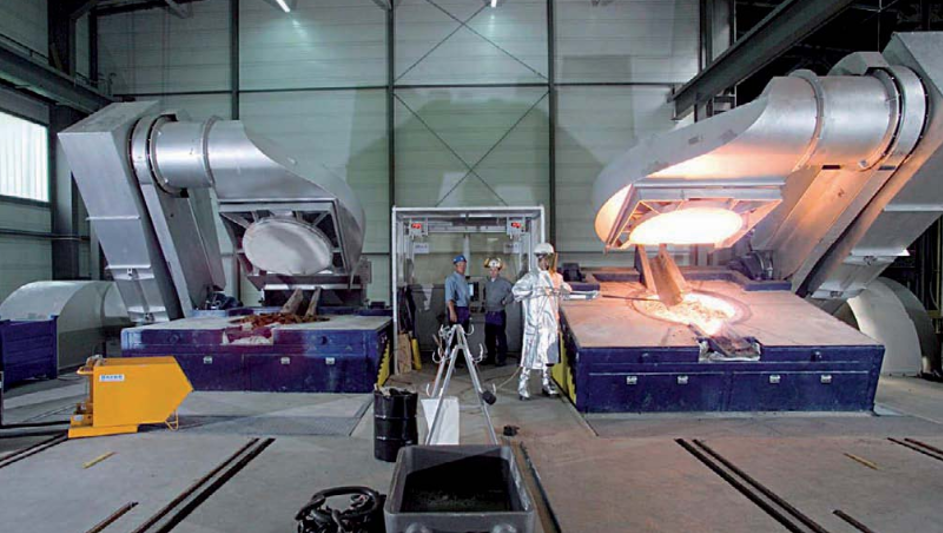
The formation of electromagnetic fields leads to the generation of electromagnetic forces, which lead to the formation of the characteristic bath movement in the induction crucible furnace. This creates a dome-shaped bath surface (Fig. 1).
The strength of the bath movement (height of the bath top) is determined by the frequency of the alternating current, the electrical power and by the furnace geometry. It can be set specifically because it is technologically very important. The bath movement facilitates the homogenization of the melt and optimizes the stirring in of additives.
If the crucible materials and the feed materials do not specify a limit, any temperature can be reached by inductive heating.
Induction crucible furnaces can be operated with mains and medium frequencies. The type of frequency conversion, the specific furnace power and the type of start-up form the basis of different characteristics and areas of application.
Frequency conversion
Mains frequency furnaces do not require a frequency conversion device because the electrical supply network feeds the furnace directly via a transformer.
Medium-frequency furnaces operate at 200 to 10000 Hz, depending on the size and performance of the furnace, the feed and the required bath movement. A frequency converter (thyristor converter) is installed between the transformer and the furnace.
Specific furnace output
The permissible bath movement and the controllability of power and voltage limit the power that can be installed in an induction furnace.
The intensity of the bath movement becomes smaller with a higher frequency. For example, a medium-frequency furnace can be equipped with approximately three times the power compared to a mains frequency furnace with the same bath movement (applies to furnaces with a capacity of up to one ton).
In the case of larger furnaces, the power limits are set by the controllability of current and voltage in the induction coil, so that the specific outputs of these furnaces are approximately twice as high as the outputs of mains frequency furnaces of the same size.
The maximum power in high-performance medium frequency furnaces is not only determined by the bath movement (metal ejection, heavy washing of the crucible), but also by maximum current and voltage values and the coil cooling.
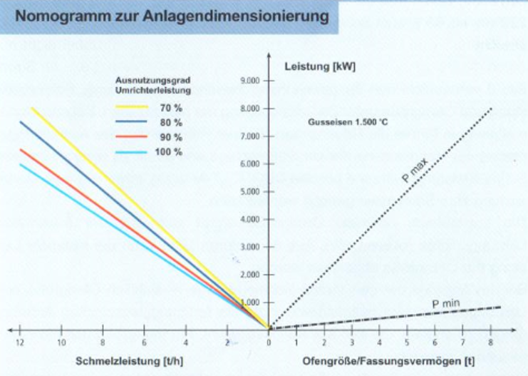
Fig. 2 shows a nomogram for system dimensioning. According to this, for example, an oven with a capacity of 8 tons should have a minimum nominal output of 800 - 1000 kW (source: Otto Junker GmbH)
Starting operation
The inductive power consumption of fixed feed material in a crucible furnace without a sump depends on the size of the feedstock D and the penetration depth d of the induced current, which decreases with increasing frequency. For economical melting, the ratio D / d should be> 6.
Due to the penetration depth, which decreases with increasing frequency, the minimum size of the inserts for starting a medium frequency furnace is significantly smaller than that for the mains frequency furnace.
In practice, this means that medium frequency furnaces can work as batch furnaces without sump without loss of performance. Mains frequency ovens, on the other hand, only work economically if they are operated with a sump of 50 to 70%.
System design
The following components belong to a powerful induction furnace melting system (according to Otto Junker GmbH)
Melting unit:
- Furnace body with coil
- Furnace chair
- Hydraulic unit
- Control panel
Electrical supply:
- Power converter transformer
- frequency converter
- Capacitor rack
- Power lines
Process control technology:
- Weighing device
- Control cabinet
- Melting processor
Auxiliary units:
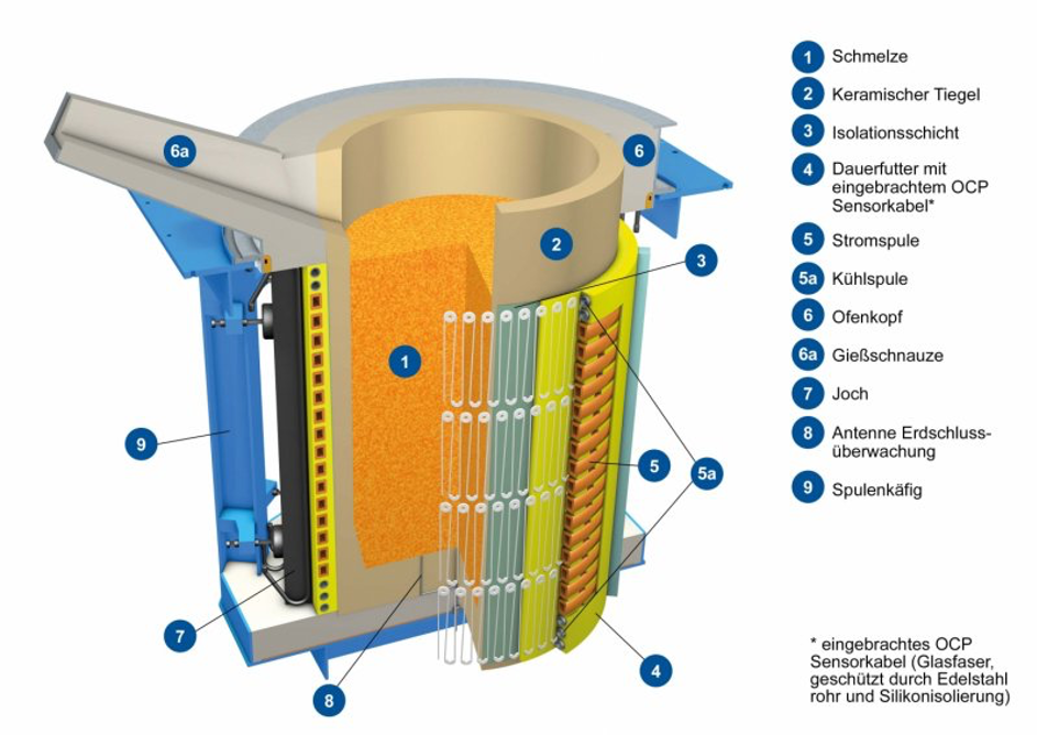
Figures 3 and 4 show the structure of such an efficient melting plant.
The furnace body consists of the cylindrical furnace coil, which surrounds the ceramic crucible. Furthermore, the yokes consisting of transformer sheet metal packages for guiding the electromagnetic field and the load-bearing steelstructure. The furnace itself is stored in the furnace chair and can be tilted hydraulically (Fig. 5). The water-cooled coil generates the magnetic field and absorbs the crucible's radial forces. The entire furnace is completed by the furnace lid and suction hood, weighing device and crucible monitoring system as well as the emergency collection pit.