Inverse chill
Inverse chill can occur in gray cast iron alloys, namely in flake and nodular graphite cast iron, preferably in the core of thick-walled castings, independent of the molding process.
These structural anomalies are crucial when assessing the finished product as they significantly deteriorate the dynamic material characteristics. In addition, this defect leads to massive treatment problems during drilling.
Particularly at risk of this defect are cylindrical and spherical designs.
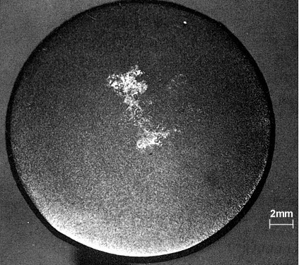
The fracture or specimen structure of the cast iron materials mentioned above shows a normal gray structure in the boundary zone, which is otherwise at risk of carbide formation. The core, however, is either white solidified (see Edge hardness, Inverse chill), shows white patches, or is coarsely mottled (Fig. 1).
In any case, this defect only occurs in thick-walled, round or spheroidally structured castings requiring long solidification times. Alloyed materials have an increased risk of this defect.
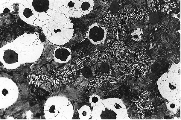
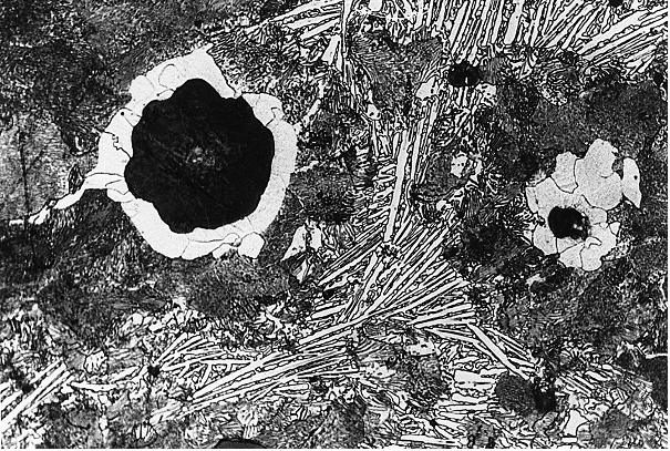
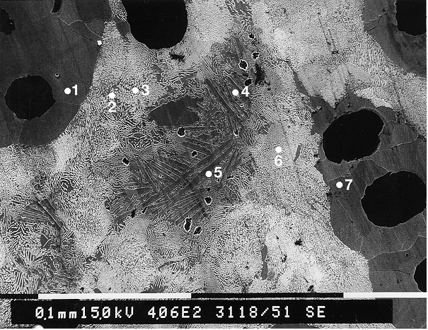
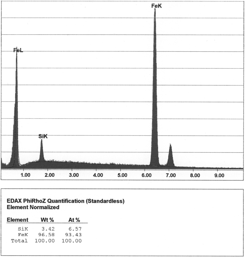
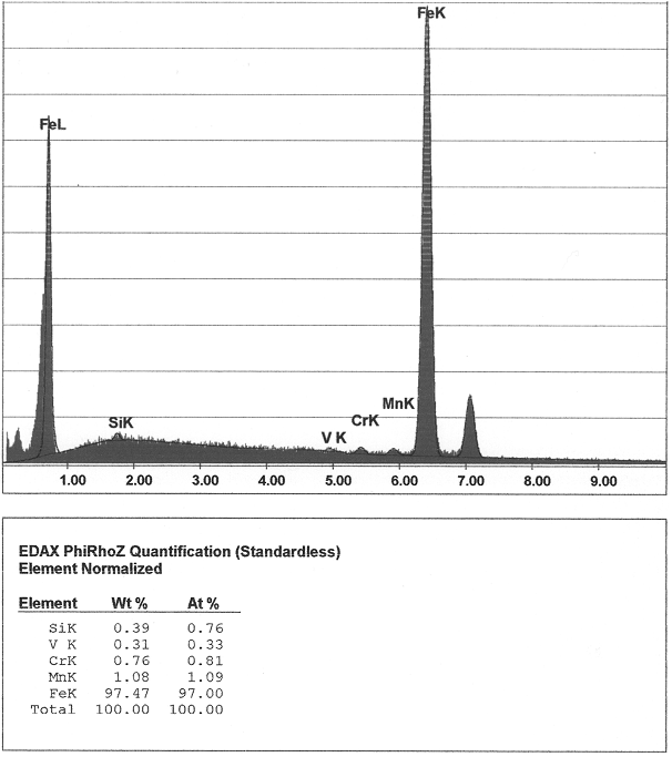
The defect is clearly visible with the naked eye on the fracture or specimen structure, more precise statements about the element distribution in the area of the defect are possible by means of EDX analyses (Figures 2 to 6).
The most likely causes of these structural degenerations are segregation-related accumulations (segregation) of carbide-forming as well as oxide- and sulfide-forming alloying elements in the center of thick-walled, mostly spheroidal or round casting designs. These areas are generally depleted in silicone. The impairment of the nucleation state of the melt is caused by severe supercooling of the eutecticsolidification temperature where the temperature falls below the temperature of the meta-stable eutectic.
Thus, the occurrence of inverse chill in gray cast iron alloys appears to be linked to certain geometries and dimensions, like those prevailing in the cylindrical sample in Fig. 1, for example. The depletion of the residual melt in silicone, but also the enrichment in carbide-forming, oxygen-affine elements, whose precipitation in form of oxidic inclusions leads to the depletion of the residual melt in dissolved oxygen, impairs the nucleation state of the solidifying melt and thus cause meta-stable solidification with formation of carbides.
The direct cause for the formation of white solidified core zones in the otherwise gray solidified cast iron is probably the phenomenon that in cylindrical and spherical castings, the cooling rate significantly increases as the crystallization front approaches the castingcore. If and when the changeover from stable to meta-stable solidification takes place is ultimately due to the depletion of the residual melt in graphitizing elements, its enrichment in carbide stabilizer, and the formation of diffusion barriers in the area of the solidification front. The carbide stabilizer chromium, manganese, titanium, and magnesium are obviously present in excessive concentrations in the area of the carbides opposite the gray solidified boundary sections. The graphitizing elements silicone and nickel are depleted this area (s. Graphitization).
Acicular carbide has proven to be particularly low in silicone. The silicone content is only a few tenth of a percent. A significant chromium accumulation was proven in the area of the white solidified core zones, with chromium being preferably concentrated in acicular carbide. The chromium contents determined are here up to five times higher than the metallic matrix. Extremely high chromium contents occur at the cell borders.
Titanium accumulations in the inverse chill were up to 2 to 6 times higher than the titanium content of the matrix. Even higher titanium contents were registered at the cell borders and at the transition from gray to white solidfication. Titanium contents of up to 0.3% with an average titanium content of 0.02% were measured in the area of the cell borders. Depletion in titanium in the ferite compared to the pearlite
Measures for prevention:
1. Reducing the contents of oxygen-affine elements, checking the charge materials for accompanying and trace elements in this respect.
2. Improving the nucleation state through optimum, possibly late mold inoculation or stream inoculation.
3. Influencing the solidification process through casting-related measures such as shortening the solidification time, ensuring even cooling, where possible.
4. Ensuring directional solidification, where possible.
5. Review of the magnesium treatment method and/or checking the treatment alloy for sulfur and phosphorus contents and rare earths.
6. Avoiding extensive magnesium excess; taking the Mg/S proportion into account.
7. Avoiding oxygen and/or hydrogen absorption, for example, due to moist charge material or insufficiently dried ladles and melting tools.
8. Pointing out the possible risks of a round, spheroidal geometry already during casting design and avoiding them, where possible.
9. Performing annealing for carbide disintegration (diffusion compensation), as necessary.