Lifting force
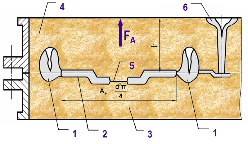
Buoyancy of the melt on the cope box or lifting force of the core due to displaced melt.In melting, the casting pressure propagates equally on all sides (“hydrostatic paradox”). In horizontally parted molds, such as the mold boxes in machine molding, this puts pressure on the upper half of the mold. The lifting force FA against the cope box for a rising casting according to Figure 1 is given in Eq. 1:
Eq. 1:
Here, Ap is the area of the casting in the mold parting projected against the cope box, h is the height of the cope box, ρl the density of the melt and g is the acceleration due to gravity. The mold boxes must therefore be weighted during casting (s. Weighting iron).The pressure against the cope box is increased even further for castings with cores due to their buoyancy (core buoyancy). Each core which is submerged in the melt is subjected to an upward vertical lifting force according to the Archimedes’ principle. The corelifting force FK corresponds exactly to the weight force of the melt volume which is displaced through the core and is usually fed into the upper half of the mold through the core prints (Eq. 2). The density of the core material does not play a role here.
Eq. 2: 
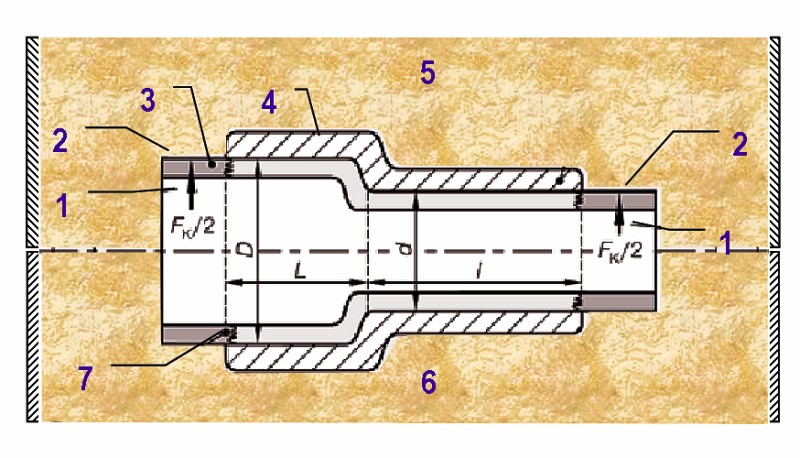
In Figure 2, the corelifting force FK is calculated for a sleeve.The core volume VK which is effective for the lifting is calculated according to Eq. 3.
Eq. 3: 
This means that the volume is the sum of both cylinder volumes without the core print which allows the exact positioning of the core in the shaped upper and lower mold halves. The lifting force according to Eq. 4 is triggered for horizontally parted molds via both core prints in the cope box.
Eq. 4: 
The core prints in Figure 2 are adapted in length to suit the core strength. If the walls are too thin or the core prints are too short, there is a risk that the core will float or shear during solidification.
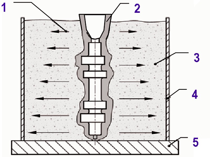
In horizontally parted molds, casting and uninterrupted solidification is only possible if the casting pressure and the buoyancy are intercepted by weighting or clamping the cope box with the drag box (Figure 3). In vertically parted sand molds, the casting pressure on the sides, as shown in Figure 4, must be intercepted by clamping, gluing and/or with the help of additional backfill, e.g. the mold halves can be supported with mold material, cut steel shot or casting gravel.
In the permanent mold process, the die locking force of the die halves is so large that this measure is usually unnecessary.