Magnetic induction casting
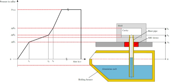
Moving an electrical conductor – in this case aluminum through a magnetic field – causes eddy currents to be generated in the conductor, which decelerate the molten metal due to the opposing field formed. The effect of this eddy current brake depends on the speed. If the flow velocity in the riser increases, so does the braking effect. When the cross-section of cavities changes significantly normal to the filling level, the magnet box decelerates the molten metal and low-turbulence mold filling ensues. This effect is self-regulating and enables low-turbulence mold filling (s. mold filling time), irrespective of complicated pressure curves that have to be adapted to the cavity. In addition, the magnet box compensates for errors that result from shifts in the pressure curve depending on the filling level.
For example, a changing furnace geometry and molten metal withdrawn through the castinglead to a deviation in pre-compression and the filling level. This shifts the pressure-change points vertically and makes them deviate from the points in the casting system. The magnetic field is controllable. This means that it can be activated and changed in a field strength from 0 to 500 mT. This possibility enables targeted influencing of the casting process. For a defined braking effect and casting process, it also allows permanent magnets to be used.
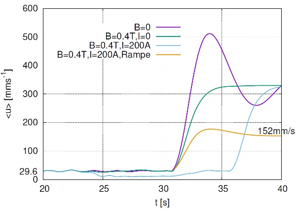
This option offers great potential for series production of the same or similar castings. Fig. 2 (Fill GmbH) shows the reduction in flow velocity in the riser pipe over time at a constant rate of pressure increase. The entry to the die is indicated on the time axis. The riser pipe with an inner diameter of 60 mm expands into a cavity with an inner diameter of 200 mm.
The magenta line B=0 indicates an overshoot and an increase in average flow velocity in the riser to over 500 mm/s at a constant rate of pressure increase of 7 mbar/s. With an activated field, the braking effect results in a reduction compared to the maximum to 270 mm/s without any overshoot.
Short-circuit current
As well as the eddy current brake caused by the magnetic field, the magnet box from Fill has been designed such that a short-circuit current transverse to the magnetic field can be sent through the molten metal. The current density caused by the short-circuit current in addition, perpendicular to the magnetic field, increases the braking effect on the molten metal to a significant extent.
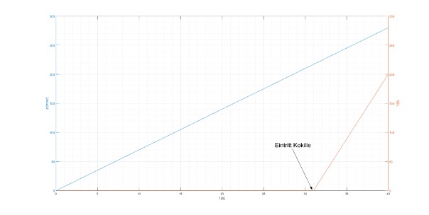
The ideal braking effect under short-circuit current can be seen in Fig. 3 (Fill GmbH). A permanently applied short-circuit current induces a time lag in the braking effect due to the field (blue line). If, on the other hand, the short-circuit current is ramped up linearly from the die ingress to 200 amps, as shown orange line in Fig. 4 (Fill GmbH) this yields an even greater braking effect that can be activated by the magnet box. The technical design permits magnetic flux densities of up to 500 mT and short-circuit currents up to 400 A.
Simulation of the new process parameters
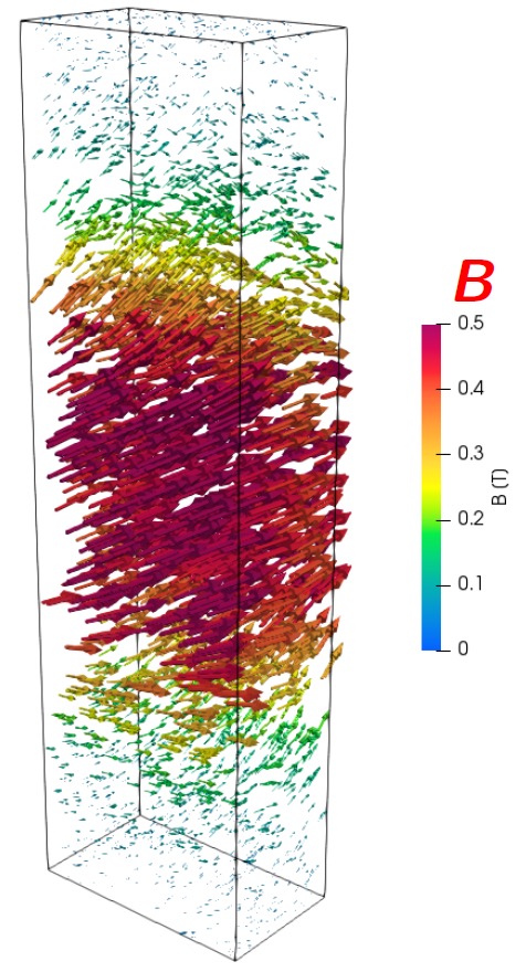
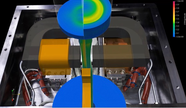
Due to the new process parameters of field strength and short-circuit current and their regulation, in addition to the pressure increase in the new magnetic induction casting process, a simulation of the magnet box has been developed (Fig. 5, Fill GmbH). The HZDR Helmholtz Center in Dresden-Rossendorf used OpenFOAM as a basis to develop implementation of the magnetic field and short-circuit current. Fig. 6 (Fill GmbH) shows the simulation of the casting process in a cylindrical cavity, on the left with braking effect, on the right without braking effect. The simulation enables optimization of the process parameters.
Components that indicate oxide inclusions or critical areas in the filling simulation can be optimized using this tool. The aim of the magnet box is to improve existing products and raise the quality rate. In the case of new products, simulation of the casting process enables improvement through virtual testing and determination of the optimum casting parameters. This allows problematic areas to be identified at an early stage and solutions to be found thanks to additional options in the process.