Mold filling control sensor
Cavity sensor for the use during the die casting process which is attached to the shot piston and records the changes of the piston speed during the injection process - during the slow shot and the mold filling phase.
One of the problematic areas if die casting is the interaction of shot chamber, casting piston and mold filling. It is very difficult to record such processes using measuring devices, in addition, problems can only be minimized, not avoided. The problems comprise among other things:
- A changed shot chamber geometry due to thermal and mechanical stresses with significant shot chamber movements
- Air or casting gasses inclusion by the melt due to the casting piston movement setting during the slow shot phase
- Melt cooling and partial solidification in the shot chamber due to heat dissipation at the shot chamber and the casting piston
- The solidified melt portion in the shot chamber is not available for mold filling. Pre-solidified areas block gate parts so that only a part of the gate is effective for mold filling
- The solidified melt part in the shot chamber is not available especially for the shrinking volume post-feeding during the cooling process in the mold cavity and for the solid/liquid transition, which results in cavities in the casting
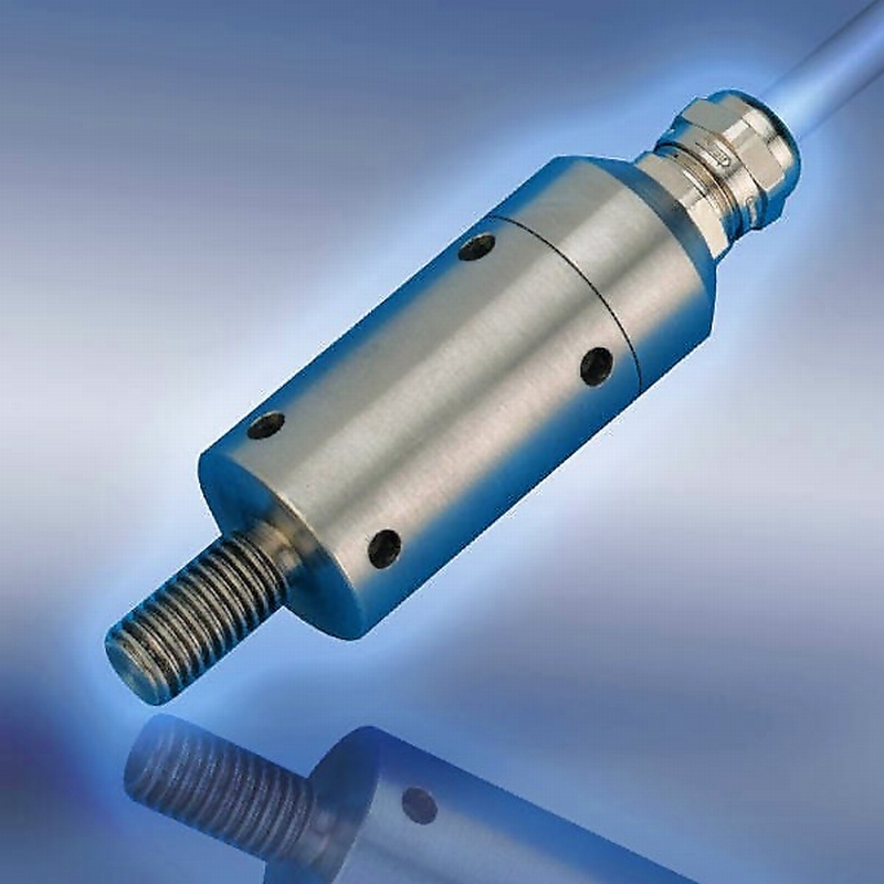
The company Electronics GmbH provides its customers with an advance mold filling control sensor (FFCS) (Fig. 1). This is the first sensor establishing a direct connection to the mold filling process which to a large extent results in a quality improvement. This sensor is attached to the shot piston. It transmits proportional signals during the mold filling process which develop due to the dynamic pressure at the transition of the geometrical conditions in the mold. The sensor has a high sensitivity and for this reason reacts to slightest speed changes. This makes it possible to obtain a specific “fingerprint” of the mold. By using the FFSC, the following conditions can be registered and fault causes can be avoided:
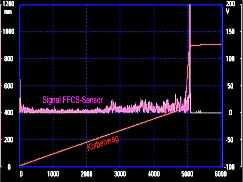
1. Fitful starting and corrugation in the first phase (noisy signal curve in Fig. 2)
2. Undesired speed change in the first phase
3. Piston squeezing
4. Piston acceleration with metal before the gate
5. High dynamic pressure due to turbulences (air inclusion)
6. Premature metal solidification in the thrid phase
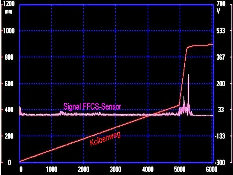
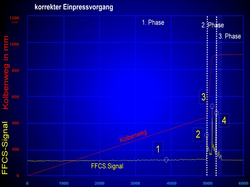
Thanks to these information on impurities, the caster now has the possibility to specifically change the injection process to achieve a more harmonious mold fillling (smooth FFCS signal curve in Fig. 3).
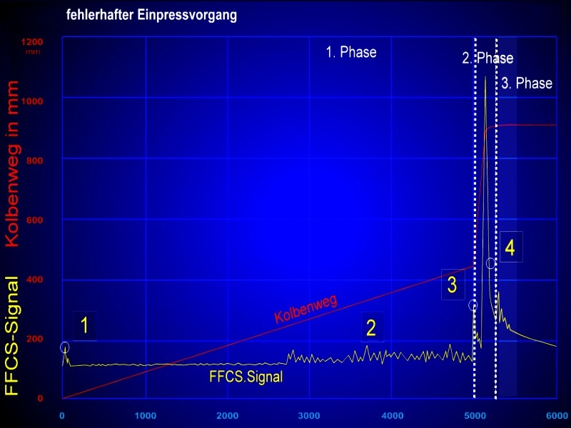
With these sensor recordings, too, sampling rates of 4 to 5kHz are required and made possible. The FFCS signal interpretation of a faulty injection process is illustrated in Fig. 4, the signal evaluation of a correct injection process is shwoin in Fig. 5.
Additional references:
Mold cavity pressure sensor, Humidity sensor, Air flow sensor, metal front contact sensor, metal front temperature sensor, multi airpipe sensor system, residual gas sensor, acoustic sensor, vacuum sensor