Mold filling time in pressure die casting
Time within which the die casting mold is filled with melt.The prerequisite for obtaining die-cast parts of high quality is the requirement that the melt must completely fill the mold cavity before solidifying or reaching too high of a solid-phase fraction. Excessive mold filling times and low flow rates during pressure die castinglead to premature solidification of the casting, resulting in an incomplete casting or cold shuts (see Cold shuts) and flow lines (flow marks).Mold filling times which are too low and associated with high melt flow rates can lead to mold erosion, soldering of the melt to the mold walls and an increased amount of entrapped air. In addition, a high dynamic pressure peak is generated at the end of mold filling which, if occurring again and again, may also result in damages to the die casting mold and closing unit or dimensional issues due to the formation of burrs. These requirements and marginal conditions must now be used to derive reliable casting times for mold filling.The flow rate required for complete and faultless mold filling is based on many factors. The following normal ranges typical in practice are applied for the flow rate in the gate (gate speedvA):
- 25 to 70m/s for aluminum alloys,
- 30 to 45m/s for brass,
- 30 to 50m/s for zinc alloys,
- 40 to 100m/s for magnesium alloys.
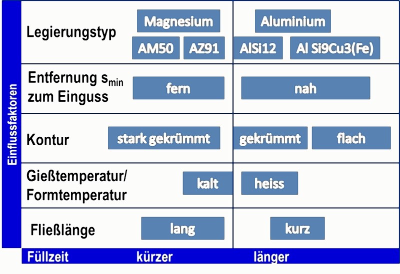
The lower values apply to relatively thick-walled, the higher values to thin-walled castings. The most important influencing factors are listed in Fig. 1.The optimum casting time depends on many factors, the most important influences being:
- Type of alloy
- Mean casting wall thickness sm
- Geometric shape of the mold cavity (i.e. the mold resistance)
- Melt temperature or solid-phase fraction in the melt during casting
- Mold temperature
- Maximum flow length inside the mold cavity
The wall thickness of the casting is considered to be one of the most important parameters. Flow rates at the lower end of the range are used for castings having a relatively high wall thickness (e.g. gearboxes or crankcases), while flow rates in the upper range are rather used for thin-walled castings (e.g. laptop housings, thin-layer castings). The casting time for filling the mold cavity can be calculated according to the following eq. 1:
Eq. 1:
Wherein:
t = casting time in s
V = casting volume in m3
AA = gate area in m2
vA = flow rate in the gate in m/sFor dimensions more typical in practice, the equation is as follows (with the mold filling time t being calculated in ms):
Eq. 2: 
vA is based on eq. 1 so that the casting time according to eq. 3 is as follows:
Eq. 3:
When using the casting mass m for calculation instead of the casting volume, then V = m/ρl and the mold filling time t is:
Eq. 4:
In practice, casting time diagrams and tables are often used for orientation, mainly established on the basis of the mean casting wall thickness and the alloy used.
Additional references:
Mold filling time
Casting time diagram
Flow rate in pressure die casting