Mold sand testing
Testing of basic mold materials according to VDG instructions P 25 to P 28 (raw and/or new sands) and testing of recirculating mold materials ready to use (see recirculating system sand) according to VDG instructions P 31 to P 43 (circulating sands).
The moste important tests are:
Water content
The water content is determined by measuring the weight loss of a drying sand sample. Additionally, according to VDG instructions P 32, a drying desiccator cabinet and an infrared lamp or a infrared fast dryer can be used. When weighing in a sample prepared according to VDG instructions P 31 of at least 20g of sand with an accuracy of 0.05g before drying and taring of x grams of sand after draying, the 
see also moisture measurement (datec Dosier- und Automationstechnik GmbH)
Sediment content
Sediments predominently consist of binding and burnt clay and mineral dusts. Their grain size amounts to < 0,02 mm, die nur nass vom Sand entfernt (abgeschlämmt) werden kann.
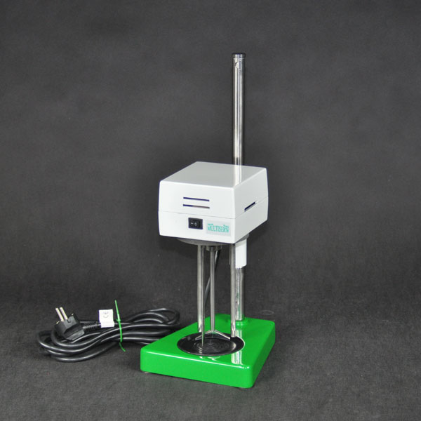
The sample prepared according to VDG instructions P 34 (testing of clay-bound mold materials) is intensely mixed and clarified after a dispersing agent was added (see also Dispersing) Fig. 1 shows a possible agitator.
The prepared sample is filled with water up to 125mm and left alone for 7-8 minutes. After that, the sediment above the suspension is syphoned up to 25mm above the bottom. The clarification (filling and syphoning) is performed twice with the same setting time and has to be repeated until the water above the sediment is clear. The clarified sand content is dried at 105 °C until the weight remains stable, cooled in the desiccator and weighed. The difference with the weighing amount at the beginning represents the mass portion of the grain class > 0.02mm and is shown in percent of dried, unclarified test mass with an accuracy of 0.1 percent.
Mesh analyses/grain size distribution
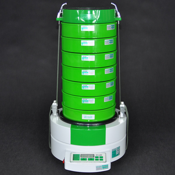
The mesh analyses and their special evaluations information on the grain size and grain distribution of a muck. For determining the grain size distribution, test sieves (analysis sieves) according to DIN ISO 3310 part 1 have to be used. For this purpose, 50 or 100g or - in case of sediment analysis - the relevant dry grain portion are placed on the upper, most coarse sieve of the sieving machine (Fig. 2) and sieved for 15 minutes in the sieving machine. Afterwards, the separate grain class portions are measured. For evaluating the sieve analysis, a cumulating frequency curve is set up (Fig. 6). After every sieving process, the mesh width, i.e. the relevant amount of grains which passed through the sieve, is shwon in percent.
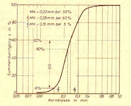
The grain size relating to a sieving process of 50 percnet is referred to as “medium grain size" (MK). The percentaged weight portion of grains between the grain sizes 4/3 MK and 2/3 MK is referred to as "degree of unifomity" (GG) (Fig. 3). Both values have to be indicated to identify the grain size distribution. The theoratically specific grain surface indicates the surface of one sand weight unit, assuming that all sand grains are globated, and has to be calculated according to to VDG instricutions p 34.
In the US, the AFSgrain size number is always shown fir identifying a sand, in Germany this is often the case. The relevance of the grain fineness number can be ascribed to the fact that this values is proportional with the number of grains per unit of weight and with the specific surface area of the sand. For calculation of the AFS grain fineness number, the value of the theoretic specific surface area is multiplied by the factor 0.57.
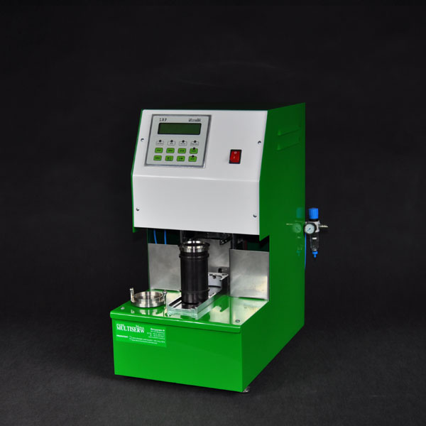
Compressive strength
Using a universal testing device (Fig. 4), the standard test item (diameter of 50mm, compressed with three rams according to VDG instructions P 38), produced with a rammer (Fig. 5) is tested for compressive strength. The values are shown directly on the test device display in N/cm2, whereas a loading rate of approximately 25g/cm2 per second has to be maintained. The compressive strength of samples with adequate water water contents is referred to as green compressive strength strength . The average value of all three measures is authoritative for all testings for compressive strength, if the single values do not deviate for more the ± 5 percent from the average value. Resistance to shearing and cleavage
Exchangeable mounting plates on testing devices for compressive strength make the determination of resistance to shearing and cleavage possible. For very low and high resistances going beyond the area of the device additional devices were developed which can be used for testing resistances in these areas, too. The resistance to shearing of samples with adequate water contents is referred to as green shearing strength, as the testing of samples with adequate water contents is referred to as green cleavage strength.
Wet tensile strength
This strength can be measured by using the testing device for wet tensile strength shown in Fig. 6. The sample shape is identical to the one for other resistance tests, however, instead of a lid a ring is put on the cylindrical box The compressed sample contained in box and ring a heated up in the device so that a soaked area underneath the heated surface develops. The ring is pulled off by a pneumatic device and the tensile strength of the soaked area is measured. The wet tensile strength is shown on the display in in N/cm2. The display shows the average value value of 3 measures (cfr. VDG instructions P 38,). Bending strength, tensile strength
In this case, too, the strength testing device can be equipped with different appliances to determine bending and tensile strength . Using special testing devices, the green tensile strength of betonite-bound molding sands can be determined.
The universal testing device shown in Fig. 4 can be used for measuring the green tensile strength. The device is also able to perfom measurements on laboratory samples. The laboratory sample form deviates from the standard test item. The measurement error margin depends on the molding sand composition and may amount to ~ 8 percent in case of laboratory tests and even more in case of functional tests. It should be mentioned that green tensile strength of betonite-bound sands can also be calculated from cleavage strength.
Form strength testing
An electronic strength tester (form strength tester) uses an oscillating quartz sensor to perform a practically pathless force measurement. The force measured corresponds to the penetration resistance as a measure of mold strength. The device has a digital indicator and a multi-function button. It measures and saves the maximal value in N/cm2 or psi, automatically calibrates the zero point and automatically switches off. The measured value is saved.
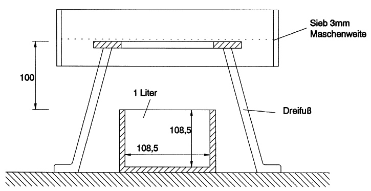
Compaction and bulk weight
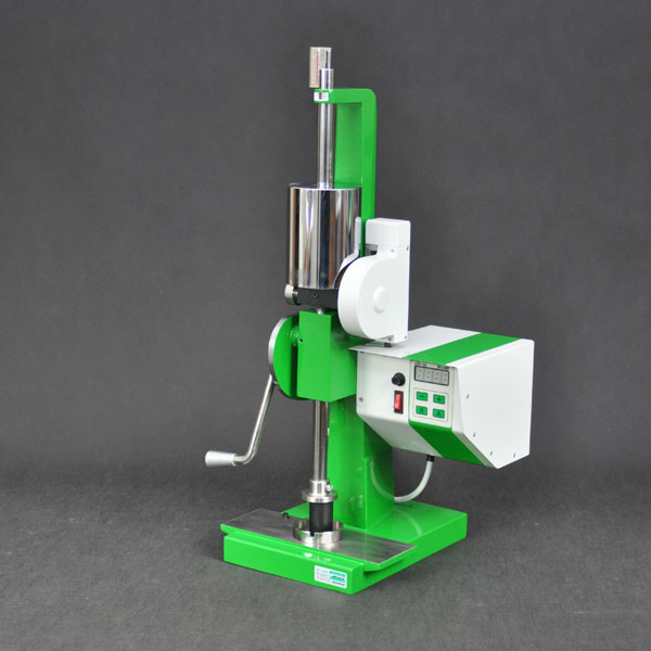
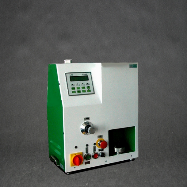
The compaction of betonite-bound mold materials has an important role when testing molding materials. However, the bulk weight or density can be tested as an alternative (Fig. 7). For determining the bulk weight (bulk density of the fillling), the molding material is sieved into a liter vessel with a height and a diameter of 108.5mm until it is completely filled. A sieve with a mesh width of 3mm has to be used. This siebe fabric has to be held 10cm above the liter vessel by an adequate appliance. The angle of repose is wiped off with a knife with a linear edge so that that molding material contained in the measuring vessel is not compressed. The measuring vessel content shall be weighed accurated to 1g. The bulk weight (SG) to be indicated is determined on the basis of 3 measuring values. Fig. 8 shows a direct link between bulk weight and compaction.A device with an extended application area is shown in Fig. 9. It can be used for the most important tests of physical sand characteristic values: Compaction, compressive strength, bending strength, double cross shearing strength, green tensile strength, wet tensile strength, gas permeability, cleavage strength. All characteristics were tested under constant conditions. All data are saved online and can be evaluated and protocolled by additional devices (computer, printer).Gas permeability
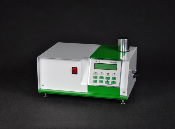
For testing the gas permeability we refer to VDG instructions P 41. A required device is shown in Fig. 10 where air with a defined pressure is pressed into and/or through the sample.
The gas permeability value is indicated without dimensions. The gas permeability to be indicated is calculated on the basis of three measurements. Hardened, cylindrical standard test items can be attached to the gas permeability device by using special clamping sleeves. Tendency towards defects
Due to the radiant heat of liquid metal, the following processes can be found on green sand molds surfaces during the casting process: Humidty from the mold surface evaporates and the water vapor condenses in a lower, colder mold area. The higher humidity content causes a considerable reduction of the sand strength in the condensation area. The tensile strength in this condensation area is referred to as wet tensile strength. At the same time, the quartz extension (sand extension) causes pressure tensions in hotter surface areas which can result in sand layers coming off from the mold cod along the condensation zone. Such sand extension defect can be seen as scab at the casting. The link between the tendency towards defects (sand extensions defect such as scabs and rat tails) of a mold sand, its wet tensile strength and its compressive stress can be shown by the following relation:
i.e. the higher pressure tensions become, the higher the tendency towards defects, whereas an increasing wet tensile strength works against it. For measuring the compressive stress, the compressive stress testing device can be used.