Nodular graphite cast iron
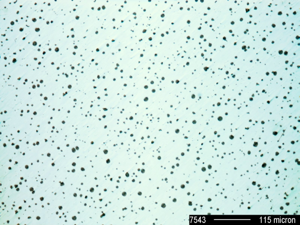
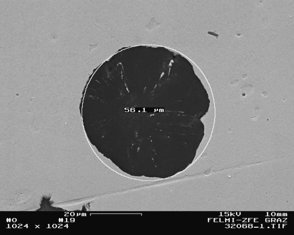
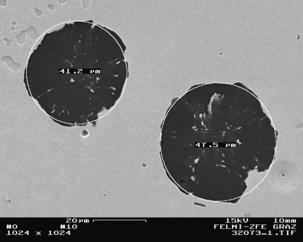
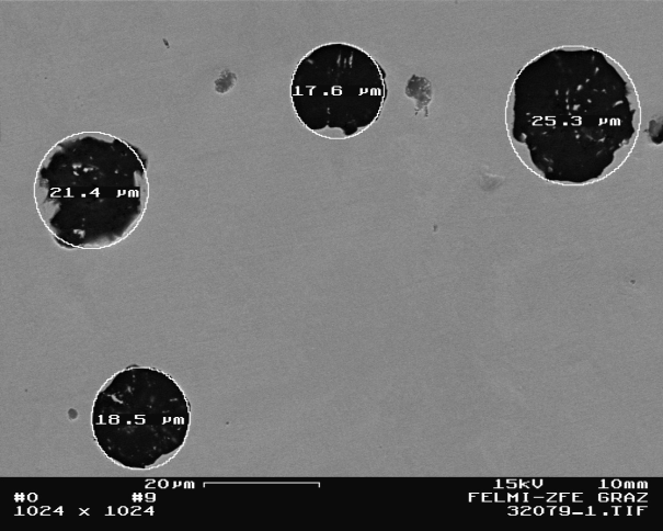
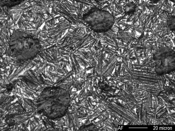
Cast iron with nodular graphite is an iron-carbon casting material with carbon being present in form of nodular graphite particles (Figure 1). It is also referred to as ductile iron.
Its properties depend on the material structure (s. Structure formation of cast iron). The standard DIN EN 1563 defines the grades and the corresponding requirements for ductile iron. The values for mechanical properties of these materials are only applicable for castings that are cast in sand molds and have comparable temperature conductivity.
The standard specifies classification on the basis of mechanical properties; These properties are tested using mechanically machined specimen produced from separately cast workpieces, cast-on specimen and specimen taken out of the casting.
Manufacturing
The charge material use for melting of base iron are pig iron, scrap steel and type-specific returns. Since definition of the structural properties, and eventually also the quality of the cast parts, already takes place during charge make-up, the selection of the type of pig iron and the suitable grade and quantity of scrap steel is of particular importance. The basic prerequisites are low contents of phosphorous and sulfur as well as such accompanying elements that have a negative influence on nodularization (so-called interference elements, such as titanium Ti, arsenic As, lead Pb, tin Sn, antimony Sb, bismuth Bi, and the like) and on formation of the metal matrix (so-called carbide formers, such as chromium Cr, molybdenum Mo, vanadium V, manganese Mn).
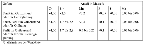
Another criterion for selection of pig iron and steel is the manganese content and for specific types (EN-GJS-400-18-LT) also the silicon content. If production of ferritic ductile iron is intended, the manganese content ought to be < 0.25 %. For pearlitic/ferritic or purely pearlitic grates (EN-GJS-800-2) the mangenese content must be higher, taking into account the wall thicknesses of the parts. Guide values for the chemical composition of unalloyed ductile iron are given in Table 1.
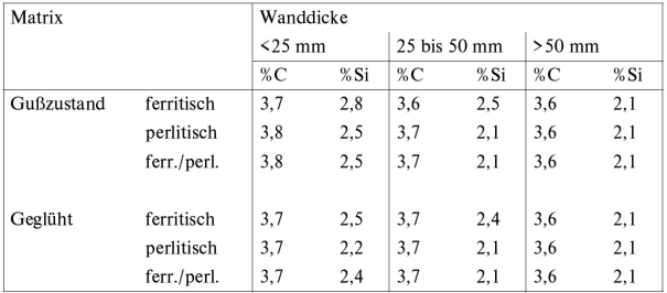
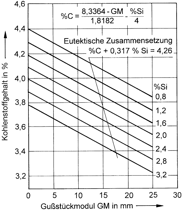
In general it is possible to produce different grates of ductile iron, both in cast condition without heat treatment, and with heat treatment. For production in cast condition, the chemical composition must be defined such that either ferritic, pearlitic, or ferritic/pearlitic structures are obtained depending on requirements, taking into account the cooling rate inside the mold and the wall thicknesses of the cast part (Table 2 and Figure 2).
For production of a base melt for GJS, generally all types of melting devices suitable for cast iron production can be used. However, the different types of melting devices produce melts in different qualities. Depending on the production program and operating conditions, to obtain nodular graphite cast iron the base iron is predominantly melted using the following processes:
- Melting in crucible induction furnaces (Simplex method)
- Melting in cupola furnaces or electric-arc furnaces, potentially also in rotary kilns, subesequently transfer into induction furnace (crucible or channel furnace) for analysis and temperature correction (Duplex method)
The correct selection of the magnesium treatment method for the respective application cases is critical for the quality level, efficiency, and production process of GJS making. As general rule, three process steps are required that cause nodularity in the graphite, on one hand, and the required matrix, on the other hand.
- Desulfurization
- Magnesium treatment
- Inoculation
With the pure magnesium process, desulfurization and magnesium treatment may be performed in one step for some applications.
The initial sulfur content in base iron is of great importance for successful magnesium treatment. To ensure technically and economically ideal magnesium treatment, the initial sulfur content must be < 0.02% if magnesium is added in form of a master alloy. Treatment with pure magnesium allows for higher sulfur contents, however, the percentage must be known exactly. The greater it is in the base iron, the sooner it is likely for reaction products, e.g. manganese sulfide, to occur and for inclusions to remain in the casting. Therefore, desulphurization is also partly necessary.
Because of its low density and low boiling point, insertion of magnesium directly into the melt is not readily possible. The issue of safe incorporation is therefore resolved by producing a magnesium alloy with other metals (nickel, silicon, copper). The vapor pressure is considerably decreased by this transformation of magnesium into metallic compounds so that safe operation is guaranteed. The products of this process are referred to as master alloys and are usually incorporated into the melt by means of the tundish-cover or sandwich process.
Master alloys with higher magnesium content (approx. 35 %) are incorporated into the filled ladle with the help of an immersion bell. It is mandatory to incorporate pure magnesium into the molten metal in closed treatment vessels. In this context, it is predominantly the converter process according to Georg Fischer and implementation of an immersion bell that have been established in practice. The inmold method is a special process in that the master alloy with a low magnesium content is positioned in a reaction chamber directly in the casting mold and that the poured iron with a particularly low sulfur content reacts with the master alloy inside the mold. Chamber size, pouring rate, and dissolving properties of the master alloy must be carefully adapted to one another.
After magnesium treatment, so-named inoculation (q. v.) of the magnesium-treated melt must be carried out (this does not apply for the inmold process, since inoculation already takes place during treatment). In addition to the carefully directed graphite precipitation (number and size of spherolites), adjustment of a favorable nucleation state also results in obtaining the required matrix along with the desired properties.
Structural characteristics
The mechanical properties of casting materials are not determined by the matrix alone but also by the type, shape and distribution of the incorporated graphite. The incorporated graphite reduce the material’s mechanical properties, with globular graphite formation causing the notch effect to reach a minimum. In this way, the mechanical properties of GJS are primarily influenced by the matrix in contrast to those of GJL. In comparison with flake graphite case iron (GJL), the strength and plasticity properties improve by leaps and bounds.
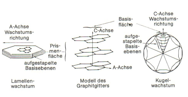
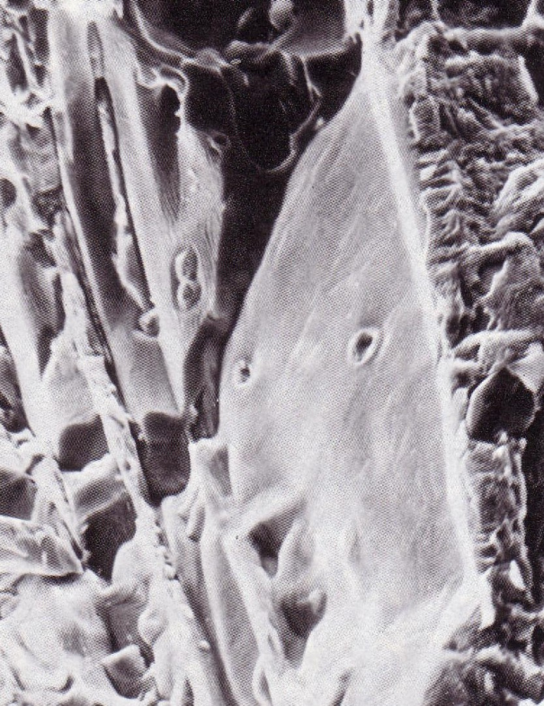
After cooling of the melt to liquidus temperature, solidification starts with precipitation of primary austenite (γ iron) in the form of tree-shaped crystals (dendrites). When reaching the eutectic temperature range, eutectic graphite and eutecticaustenite diffuse of the residual melt amount that is still present by then; this process takes place until the melt is completely used up and solidified. Growth of lamellae or spherolites is induced by the fact that in the first case the graphite crystal preferably grows in longitudinal direction (a-axis), and in the second case in latitude direction (c-axis or basic plane) (Fig. 3).
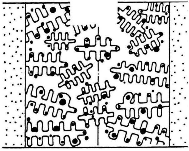
The solidification sequence of gray cast iron or ductile iron differs in two other important aspects, other than graphite formation: Solidification of gray cast iron predominantly results in shell formation, while ductile iron displays mushy solidification (Figure 4). With shell-forming solidification, the freezing front grows inwards and consumes the residual melt in the center so that a shell with various layers is formed.
Mushy solidification is the exact opposite of the above. The melt thickens, similar to pulp, due to crystal precipitation throughout the melt while crystal growth uses up the melt; there is no distinct solidification front.
In nodular graphite cast iron, the eutectic graphite and austenite precipitation takes place in temporal and local isolation. At the beginning of eutecticsolidification, austenite predominates and therefore solidification shrinkage is caused at first; only later, after full set-in of graphite precipitation expansion prevails. Eutectic graphite precipitation begins a the crystallization nuclei. In nodular graphite cast iron, the number of graphite nodules is equal the amount of nuclei. From the above it can therefore be concluded that, apart from deviations in graphite nodule formation from ideal form VI, there is only the nodule count and nodule size available as additional structure parameters for graphite formation.
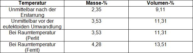
Graphite formation in nodular graphite cast iron is largely dependent on the content of free carbon, on cooling conditions (wall thickness, molding material), and on the respective crystallization conditions. Crystallization takes place by formation of eutectic grains, in which graphite is present in coherent spatial form. Conventient nucleation conditions and high cooling rates increase the number of grains (nuclei) and cause fine-grain formation. In Table 3 the graphite quantities for eutectic cast iron deduced from the iron-carbon phase diagram are specified for various temperatures.
It can be seen that the graphite quantity in the structure is significantly increased over the course of cooling during the stage between solidification and eutectoid transformation, even under equilibrium conditions, and that during completely ferritic transition of austenite, the greatest amount of graphite is precipitated. In austenite that is oversaturated with carbon, even more graphite will precipitate during ferrite formation, or during transformation to pearlite, an increased number of cementite will form.
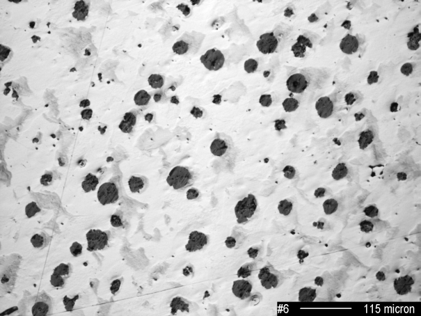
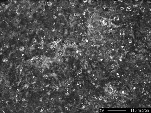
However, this has little to no effect on the graphite form so that the characteristics of graphite described below are generally applicable for all qualities (unalloyed, alloyed, austempered, heat-treated, etc.). It is a matter of course that iron alloys always contain a number of accompanying elements, that are imported e.g. through the raw iron, the scrap steel, etc. used. Among these elements there are some that impair formation of nodular graphite if they exceed a specified content limit. This results in what is known as graphite degeneration, which has a highly detrimental effect on material properties and may cause the part to be classified as reject. These types of structure formations are explained in detail in another entry. The same applies for too high or too low residual magnesium contents. The influence of the graphite in ductile iron is less evident than in comparison with GJL. Consequently, it is possible to widely and variedly adjust the mechanical and dynamic properties by corresponding changes in the matrix, provided that optimum nucleation conditions are available. The nodule count increases proportionally with a decrease in wall thickness; this widely known fact is illustrated by Figures 5 to 7.
Metal matrix
Control and formation of the matrix is based on the uniqueness of the dual iron-carbon system (s. Iron-carbon phase diagram), which has made ferrous metals the most important metal materials by far. Characteristics are:
- Transformation of the cubic face-centered austenite grid into cubic body-centeredferrite grid and
- Insolubility of carbon in ferrite, which results in preciitation of carbon and thus allows for precipitation of carbon both in the form of graphite and in the form of iron carbinde.
In this way it is generally possible to obtain five different transformation products and/or the corresponding matrices:
1. Ferrite (Fig. 8), with the transformation of austenite taking place in the stable system. In microscopic scale of the structure, this represents long-term diffusion. It takes relatively long and/or requires comparatively high temperature levels. With a ferritic matrix, maximum toughness, thermal resistance and good machining properties are obtained.
2. Pearlite (Fig. 9), in which carbon is precipitated as cementite in the form lamellae (or flakes) along with ferrite. The transformation to pearlite in the meta-stable system corresponds to medium-term diffusion of carbon. The distance between the lamellae is decreased the lower the temperature falls.
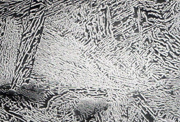
3. Austempered ductile iron (Fig. 10), below a temperature of 400 to 500 °C the transformation mentioned above is no longer possible; instead, short-term diffusion takes place, which initially generates ferrite. The carbon displaced from the ferrite accumulates in the austenite, whose carbon content may increase up to 2 % due to this process. This stabilizes austenite down to low temperatures and the resulting structure comprises a mixture of finely acicular ferrite and austenite. That is the structure aimed for in ADI. A critical prerequisite for successful performance of these measures for improvement of strength and toughness combinations is undisturbed formation of the solidification structure.
4. Bainite (Fig. 11), forming upon longer hold times in the temperature range between 400 and 240 °C because the rich-in-carbon austenite in austempered ductile iron segregates to form ferrite and acicular carbide so that bainite (known from steel production) is obtained. This structure is unwanted in ADI.
5. Martensite (Fig 12) is formed through diffusion-free transformation of austenite. Precipitation of carbides is suppressed and the α solid solution oversaturated with carbon is distorted tetragonally. Below a temperature level of approx. 240 °C carbon diffusion is not longer possible, the austenite lattice collapses without diffusion. These transformation processes of austenite can be strategically influenced by heat treatment and/or alloying elements.
Solidification structure
Real alloying compositions, as well as, solidification and transformation processes taking plate under imbalance conditions lead to modifications in equilibrium structures. In this way structures are formed under practical conditions, which are not listed in the iron carbon phase diagram Due to the composition possibilities (in the range between hypoeutectic and hypereutectic), the solidification structure of iron castings is determined by the primary and eutectic crystallization occurring within the stable or meta-stable iron-carbon systems, depending on alloying composition, cooling rate, and nucleation conditions. Consequently, the solidification structure is made up of quantity size, shape, and distribution of the graphite, extent, amount and distribution of alloying element segregations, free carbides, as well as the quantity, size, count, distribution, and type of hollow cavities (micro-shrinkage, cracks, pores) and non-metallic inclusions, such as slags (s. Slag inclusions).
This structure is always present in iron castings for technical purposes; its proportion depends on the ways and methods of melt control, the charge materials, the alloys and, not least, on the design of the cast part (wall thickness). It does not necessarily produce reject parts, however, in the worst case it may have a negative effect on mechanical properties of the material.
It is not possible to retroactively change this primary structure, except during disintegration annealing of free carbides (s. Carbide disintegration annealing), which has gained great technical importance, particularly in ingot and centrifugal casting. Even with an optimized matrix (pearlite/ferrite ratio, fine-grain structure of pearlite), incorrectly formed primary structures cannot be compensated.
Additional references:
Metal matrix of cast iron
Structure formation of cast iron