Oil temperature controller
Temperature controller with an oil forced circulation system for automatic regulation of the operating temperature of a metal permanent mold (particularly die casting molds).
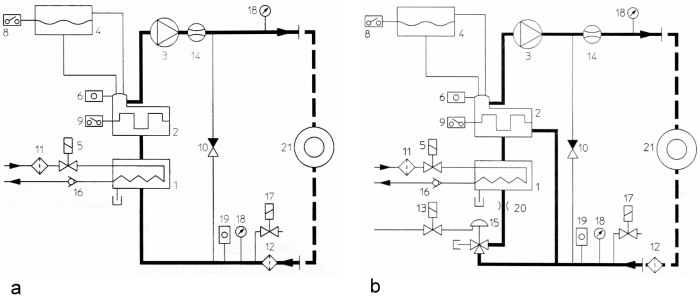
For safety reasons, the forced circulation system in standard pumps is usually used for heat transfer oil starting at flow temperatures of over 150°C and for applications with excessive heating. The system is shown in Figure 1a and consists of a heater (2) with defined flow relationships, the so-called forced circulation heater, which prevents a thermal overload of the heat transfer medium when laid out correctly. The heater usually consists of a pipe with a built in heater which heat transfer oil flows around and which has baffle plates for the forced circulation of the oil. In addition to the structural components, the level control (8), safety thermostat (9) and automatic cut-out and temperature relay for the pump motor, for safety reasons, it also has an expansion tank (4), a bypass (10) and a flow monitor (14). The expansion tank separates the circulating hot oil from the atmosphere which prevents disadvantageous accelerated aging of the oil due to oxidation. For very high temperatures in the supply line which lie overs the boiling point of the oil, an inert gas covering is used in the expansion tank (pressurized covering with nitrogen). The bypass is connected to the consumer in parallel and has the following tasks:
- To protect the pump and pump motor against overload
- To maintain the minimum flow amount in the devices in the case of insufficient circulation in the consumer so that the maximum film temperature in the heater is not exceeded and the heat transfer oil is not overloaded
- To protect the consumer to which it is connected against pressure that is too high
- To adjust the flow rate at the consumer (especially for pumps with a high flow capacity)
Like the bypass, the flow monitor serves the monitoring of the circulation. If the minimum flow rate is not reached or there is minimum pressure, the heater is turned off. The flow monitoring therefore also responds when the flow in the temperature cycle breaks off for any reason and therefore provides protection against dry running and the device overheating.
The device’s safety measures which have been described such as forced circulation, expansion tank, bypass and flow gage bring the operator the following advantages:
- Minimum coking and high resistance to oxidation of the heat transfer oil and therefore longer lifetime
- Lower operating costs and greater operational safety of the temperature controller
The cooler (1) can be made of a bundle of pipes inside which the cooling water flows and around which the heat transfer oil flows. The non-return valve (16) in the cooling water outflow reduces lime-scale deposits in the cooler due to water flowing back if the outflow is not free from counter pressure. The pump (3) is usually a centrifugal or gear pump with a ring gasket, a pump with a canned motor or with a magnetic coupling.
To reduce the thermal strain on the cooler and improve the control behavior during the cooling process, the forced circulation devices for temperatures above 300°C are fitted with a bypass switch for the cooler (principle in Figure 1b). Here, during heating, the valve (15) is closed in direction 12-2. This means that the cooler is bypassed. During cooling, the valve (15) is opened in direction 12-1, which means that the heat transfer oil flows through the cooler (1) and directly via the heater (2). The temperature regulator in the device controls the three-way valve via the magnetic valve (13).
This cooler bypass switch displays the following advantages:
- Significantly improved temperature control as no strong undershooting which is independent of the cooling capacity occurs
- Reduction of the thermal shock to the heat exchanger during the cooling process and safer operation
- Lower tendency for lime-scale to form
- No steam emissions at the beginning and end of cooling
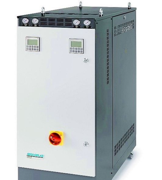
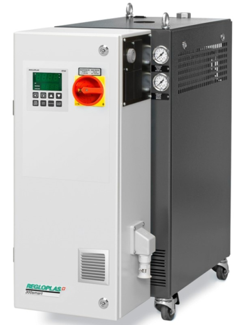
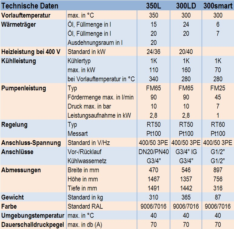
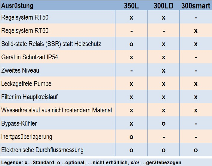
The advantages of devices with forced circulation lie in the achievement of a maximum flow temperature of up to 350°C, and therefore in less oxidation of the oil and longer oil lifetime. No odor is formed, no combustible oil fumes are emitted and the devices display high operational safety. However, forced circulation devices are more expensive than temperature controllers with bath heating and their construction is considerably more complex. Figure 2 and Figure 3 (Regloplas AG) show the construction of two oil temperature controllers. An overview of the technical data for selected oil temperature controllers is given in Table 1; the equipment which they have is listed in Table 2.
Further references:
Pressurized water unit
Mold temperature
Die heating and cooling
Heating unit
Thermal balance