Orientation Imaging
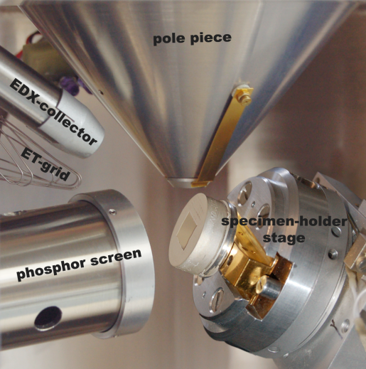
A special, strainless prepared sample is scanned by the incoming primary electron beam with an angle of 70 degrees.
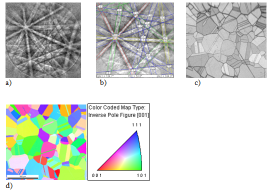
A certain quantity of the back-scattered electrons is bent at the crystal lattice according to the Bragg law (n · λ = 2 · dhkl · sinθ). This results in a diffraction image, the so-called Kikuchi pattern. This pattern consists of parallel line pairs. Each of these pairs (Kikuchi band) has a certain width which corresponds to the relevant crystal level. The intersection of these lines corresponds to the area axes.
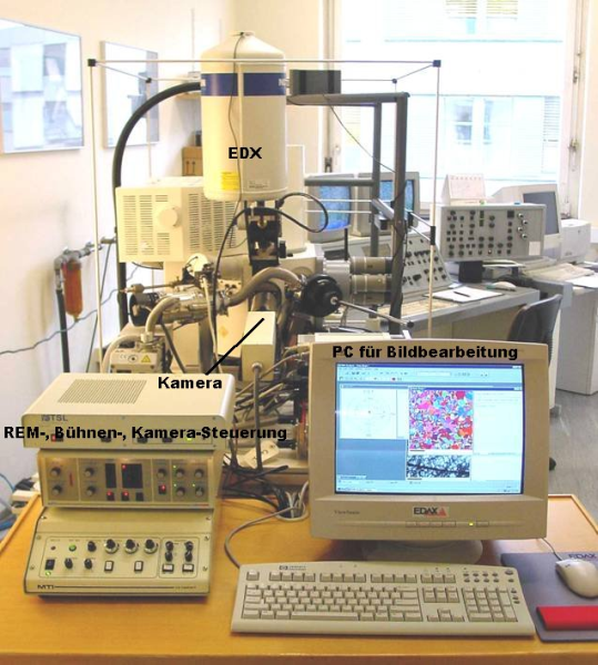
For each point, the diffraction image is recorded by a scintillator of CCD camera und induced by a computerized system through Hough transformation. Thanks to this, the relevant orientation can be assigned to each point. Grain and/or phase boundaries, crystal orientation (such as texture), grain size distribution, recrystallization degree, etc. can be determined. Since the Kikuchi pattern depends on the crystal system, phases which analytically are identical can be differentiated (e.g. ferrite vs. austenite).
Literature:
Schröttner H. : Die Elektronenmikroskopie in der Materialforschung / Electron Microscopy in Materials Research
Weinberger, T.; Führer, B.; Khosa, S. U.; Enzinger, N.; Cerjak, H.-H.; Schröttner, H.; Mitsche, S.:
Evolution of Microstructure and Properties for Friction Stir Welded Martensitic Precipitation-Hardening Steels