Pin holes
Bubbles or cavities predominantly occurring at the outside of the casting or just below the surface of flake, nodular or compacted graphite iron, malleable cast iron, and cast steel castings.
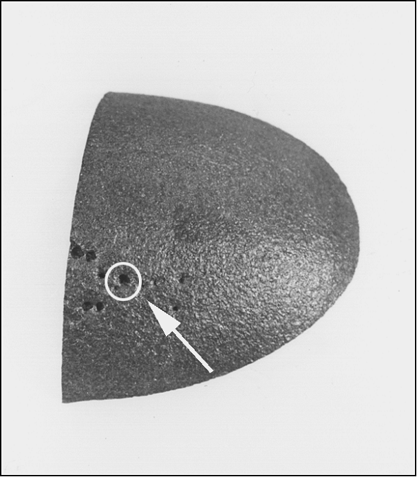
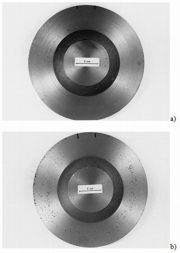
Pin holes occur individually and over a large area and can affect all casting sections. In many cases they are not visible until after machining, but always with the naked eye.
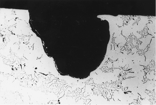
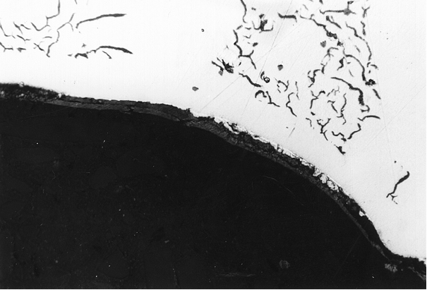
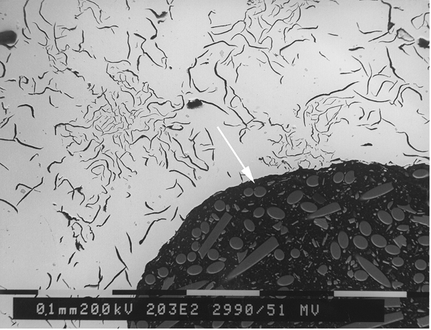
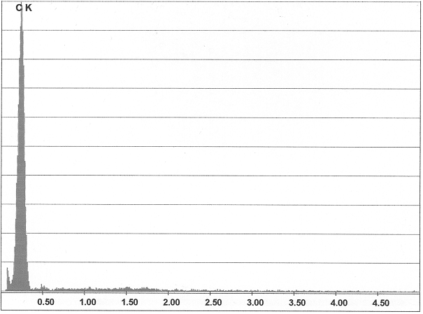
The appearance of pin holes ranges from nodular bare metal bubbles or bubbles covered with graphite skins to larger cavities of irregular shape accompanied by slags or oxidation (Figures 1 to 6).
They are referred to as hydrogen pin holes and hydrogen-nitrogen pin holes, which cannot be distinguished from each other, and as CO-slagpin holes. Specific properties of the iron, on the one hand, and specific properties of the mold material system, on the other handare known to be possible root causes of these defects. In practice, the formation of pin holes is often not caused by an individual factor, but by the cumulative effect of several overlapping factors. Pin holes can lead to Impairments in coatings such as enameling hot-dip galvanizing, powder coatings etc. With respect to the structural load-bearing capacity, this defect has hardly any influence, particularly in case of ductile cast iron types and low stress levels. With machined functional surfaces which also have to be impervious, this defect leads to rejection. Moreover, if the defect occurs in an unfavorable location, this will impair the fatigue strength, and consequently pin holes cannot be tolerated in safety components subject to fatigue loading.
The formation of hydrogen and hydrogen-nitrogen pin holes is a process in three stages:
- Reaction of the water vapor with other elements in the iron. This leads to the formation of metallic oxides and atomic hydrogen which diffuses into the liquid metal. Nitrogen-hydrogen compounds are broken down in similar ways and can also diffuse into the liquid metal.
- Formation of micro gas bubbles due to reaction of the metallic oxides with the carbon of the melt.
- Diffusion of hydrogen and potentially nitrogen into the micro gas bubbles and size increase of the bubbles.
These are the causes of pin hole formation from a metallurgic point of view:
- Excessive hydrogen content in the melt which may be caused by hydrogen carriers such as moisture of charge materials in general, in particular fine-grained, unprotected ferro-alloys, which often accumulate water, highly rusty charge materials (accumulated OH groups), oils and emulsions releasing hydrocarbons, and ultimately by the impact of an increased humidity itself
- Excessive nitrogen content in the melt which may be introduced by nitrogen carriers such as scrap steel (up to 130ppm N, max. 200ppm N), rail steel (up to 170ppm N), pig iron (10 to 60ppm N), carburization agents (from 0.11 x 10⁴ppm to 1675 x 104ppm N)
The nitrogen content in the casting is within the range of 40 to 140ppm, thus making it possible for degassing to occur in case of externally excited bubble formation, e.g. by inductive stirring. The critical limit for the formation of pin holes is often indicated with 80 to 100ppm, although lower contents in connection with CO precipitations can already be critical.
In comparison with cast steel, cast iron has a lower tendency to gas absorption as carbon and silicon decrease the solubility and thus the readiness to absorb hydrogen and nitrogen. Consequently, a cast iron melt with a lower degree of saturation is significantly more sensitive, which is also reflected in the frequency of defects in malleable cast iron, which naturally must have a lower degree of saturation
Chromium, molybdenum, manganese, vanadium, and titanium increase the solubility of hydrogen and nitrogen whereas it is reduced by aluminum, phosphorous, silicone, and carbon. An examination revealed that castings with the same gas content were completely intact at 70ppm Al whereas the same castings with 380ppm Al revealed severe pin hole formation. Increased aluminum contents can cause a transformation of the aluminum in the iron with the water vapor of the mold gas to aluminum oxide and hydrogen. This hydrogen then leads to bubble formation. This is where the line between purely metallurgically caused gas bubbles and the interfacial reaction between mold (core) should be drawn.
Molding material-related causes:
- Too high nitrogen contents in the mold sand with too high moisture contents.
- Unfavorable gas atmosphere in the mold cavity the causes of which originate in the type and amount of lustrous carbon formers added.
- Too high nitrogen content in core sands and/or too high nitrogen-hydrogen compounds in core mold material binders.
- Particularly in the pyrolysis of Croning core binders, large amounts of gas are released at the time where no stable marginal shell has formed yet.
The mechanism is explained as follows:
Under reduced atmosphere, ammoniac breaks down according to the eq. 1
Eq. 1:
At approximately 600°C and atmospheric pressure, the ammoniac is almost completely dissociated. During this process, the gas volume is doubled, 2mol ammoniac transform into 1mol nitrogen and 3mol hydrogen. This hydrogen gas may also react with the separated carbon monoxide according to the following eq. 2:
Eq. 2:
Insufficient degree of conditioning of the bentonite-bound mold material and therefore presence of free water, not bound in the bentonite (in the three-layer mineralmontmorillonite) which increases the risk of hydrogen formation.
In addition to the iron composition and the mold material structure, there are other factors for the occurrence of pin holes. For example, incomplete removal of the slag can lead to slag inclusions , which may act as nuclei for bubble formation. Numerous oxides are present in nodular graphite cast iron, even if the slag has been removed, and these oxides can contribute to the formation of pin holes. The slag produced during magnesium treatment also has an impact, although it is not clear whether it purely mechanically causes a surface defect or promotes gas formation.
The casting and gate technology can also have an impact on pin hole formation. A gate system with non-turbulent flow and short runners reduce the tendency for pin holes to form.
Splash balls can also be a cause for pin holes. They are oxidized and then enveloped by the casting flow. This can lead to a reaction where CO is produced which results in the formation of gas bubbles.
Measures for prevention (acc. to S. Hasse, FT&E):
- Reduce hydrogen carriers reduce, i.e. use dry charge materials, avoid highly rusty, oily charge materials.
- Reduce the nitrogen carriers (e.g. scrap steel) in the charge, for GJL, observe minimum titanium content (0.02%), if applicable. Use recirculation material in blasted condition, where possible.
- If possible, increase degree of saturation, adjust manganese to maximum 0.4% Si, reduce aluminum content (not ? 100ppm). In the presence of titanium, the negative effect of aluminum is further reinforced, with Ti contents of 0.02% and Al contents from 0.01 to 0.2% increased pin hole
- Use material with reduced aluminum contents and ensure that casting temperatures are adequately high. Low casting temperatures reinforce the tendency towards defects which is considered an indicator that pin hole formation is caused by surface oxidation of the melt during casting and solidification.
- Change the gate system such that the melt is given few opportunities for oxidation, shorten flow paths, avoid turbulences.
- In case of cast steel, keep the hydrogen content of the melt as low as possible by means of intensive cooking during the refining period. Ensure thorough pre-deoxidation and short casting times, avoid long flow paths.
- Reduction of slag formation.
- Reduce humidity content in the mold material, reduce quantity of coresand addition (nitrogen, urea), refresh with new sand, if required.
- Check the lustrous carbon content of the mold material and optimize, if required, change lustrous carbon formers, if required.
- Reduce binder quantity in resin-bonded molds and cores, if required or use other binder and/or catalysts.
- Face coat molds and cores (nitrogen-absorbing barrier face coatings), thoroughly dry water face coatings, check and optimize vents.
- Avoid inclusion of auxiliary riser materials into the mold material system.