Rotary degassing
Scavenging gas treatment of melts, whereby an injector which is submerged in the melt rotates and the scavenging gas (usually an inert gas) is distributed in the melt in small bubbles. Rotary degassing or impeller degassing is mainly used for the purification and hydrogen degassing of aluminum melts (see Hydrogen solubility).
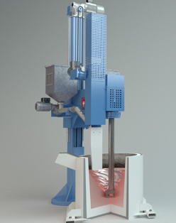
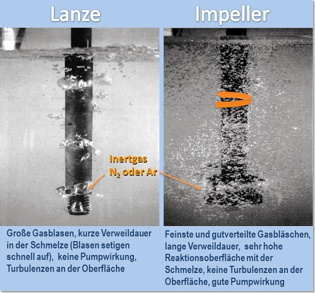
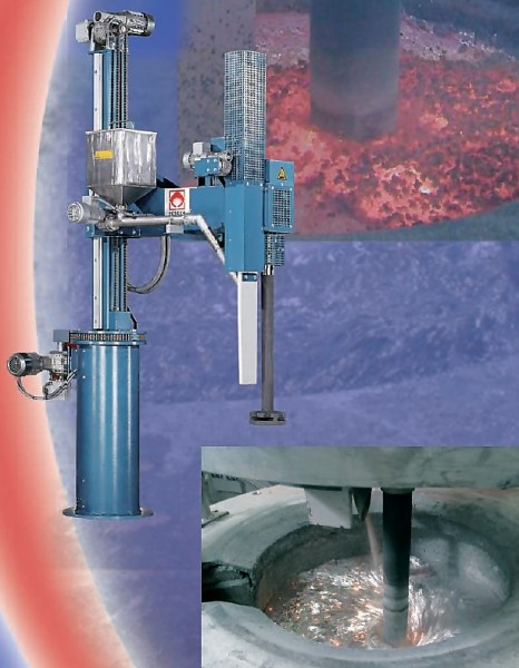
Rotary degassing devices (impeller devices) are suitable for scavenging gas treatments in the crucible or in the ladle between the furnace and casting location; the basic design follows Fig. 1, (Foseco Foundry Division Vesuvius GmbH); a rotary degassing device is shown in Fig. 2. The device is placed on the crucible or treatment container or, if it is designed as a free-standing device, the rotor goes into the ladle below it (impeller station). Through the vertical hollow shaft and the rotor on the lower end of the shaft, the scavenging gas is blown into the melt and - unlike in lance degassing - is distributed in extremely small bubbles (Fig. 3). The fine bubbles are mixed intensively with the melt by the rotation of the impeller (Fig. 4). The specially shaped rotor ensures fine distribution. The rotor and shaft are usually made of graphite. Examples of rotor shafts and heads are shown in Fig. 5.
The smaller and more frequent the scavenging bubbles, the better the melt can be degassed and also freed from (mainly oxidic) impurities. Video 1 shows the formation of fine bubbles in a test in water. The melt is homogenized at the same time. This means that a rotary degassing device does not just serve the degassing process but also, when operated correctly, the removal of oxides which remain on the surface with the baffle plate (sword).
All standard treatment gases are suitable as scavenging or purification gases. Rotary degassing is usually carried out with an inert gas which is suitable for the affected melt, e.g. nitrogen or argon for aluminum melts. In some cases, the inert scavenging gas is also mixed with low concentrations (<2.5%) of sulfur hexafluoride or chlorine. In aluminum melts, a high decrease in the hydrogen content due to the fine distribution of the scavenging gas by the rotor is achieved much more quickly than with other scavenging gas processes. With this principle - for almost any still bath surface - a very wide distribution of gas bubbles in the whole treatment container is achieved, which leads to very short treatment times with effective degassing and melt purification. < 2,5 %) dem inerten Spülgas beigemischt. In Aluminiumschmelzen wird eine hohe Senkung des Wassersstoffgehaltes infolge der Spülgas-Feinstverteilung durch den Rotor sehr viel rascher erreicht als mit anderen Spülgasverfahren. Mit diesem Prinzip wird - bei nahezu ruhender Badoberfläche - eine sehr breite Verteilung der Gasbläschen im gesamten Behandlungsgefäß erreicht, was zu sehr kurzen Behandlungszeiten mit effektiver Entgasung und Schmelzereinigung führt.
Influential factors for the optimization of the rotary degassing process are:
- Crucible size and crucible shape
- Bath level
- Immersion depth (particularly the distance between the rotor and the bottom of the crucible)
- Rotor position and rotor speed
- Sword position and immersion depth
- Length of treatment
- Gas flow
The following applies as a rule of thumb for a 600kg aluminum melt:
- Rotor speed: 400-500 mins-1
- Length of treatment: 6 - 10 mins
- Gas flow: 10 - 20 l/min Ar or N2
To improve the quality of the melt and also for metallurgic treatment (grain refinement, modification), complex degassing devices and/or melt treatment devices can be used, such as the one shown in Fig. 6 (Foseco Foundry Division Vesuvius GmbH). With these devices, a vortex is first formed by the rotor, into which the treatment which is in the form of a granulate is scattered. Then the baffle plate is put in and the degassing treatment is carried out.
A comparison of correct and incorrect operation based on evaluation of the rotation speed and the bubbles and the foam on the melt surface is given in Video 2 .
Video 2: Comparison of correct and incorrect operation of impellers, source: FT&E Foundry Technologies & Engineering GmbH
Further references:
Vacuum, Vacuum metallurgy
Partial pressure