Stress-based design
When designing castings, the stresses occurring during operation and machining must be taken into account and used a basis.
In addition, some casting materials, such as flake graphite cast iron, are particularly notch-sensitive. Compressive stresses rather than tensile and bending stresses should be applied, especially when using GJL. Notches and changing cross sections should be avoided by means of structural changes wherever possible.
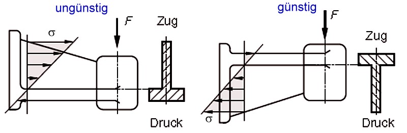
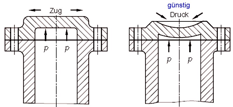
For the absorption of bending moments, such as with the wall-mounted support arm in Fig. 1, the neutral axis should be positioned such that the cross section subject to tensile stresses is larger than the one subject to compressive stresses, keeping tensile stresses low (in particular for GJL). In pressurized vessels, the tensile stresses caused by internal pressure can be converted into compressive stresses by means of structural modifications, as shown in Fig. 2.
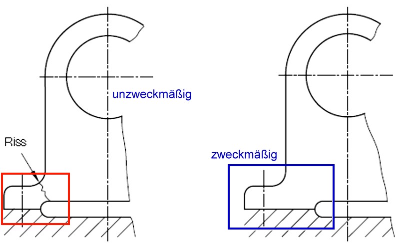
The bending stresses present in the support base of a bearing block can result in the risk of cracking with an unfavorable design (Fig. 3). Cracking can be considerably reduced when using a suitable stress-based design.
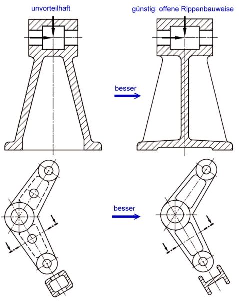
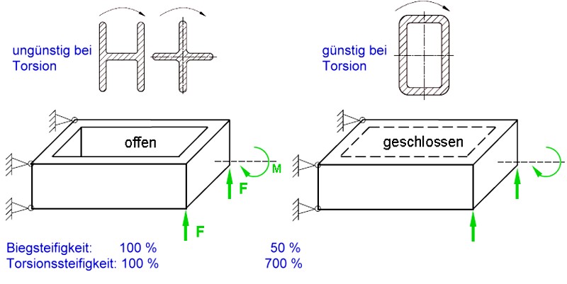
Bearing blocks and levers are usually not subject to torsional stresses. Therefore, an open rib structure (Fig. 4) can in many cases be sufficient to absorb tensile and compressive forces and can be a more favorable solution.
Subjecting an open section to torsional stresses is generally disadvantageous since large cross sections would be required to safely absorb torsional forces. Designing castings with a hollow section is more advantageous in these cases despite the more expensive core work (Fig. 5).
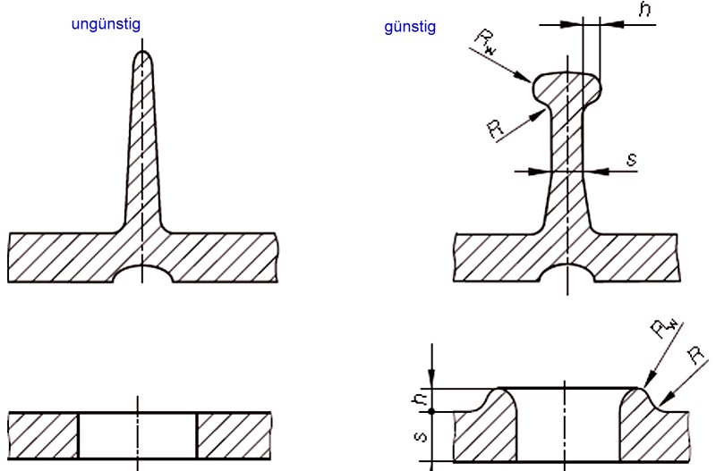
Ribs with a conically tapered or rounded shape are at risk of developing incipient cracks when subjected to alternating bending loads. Perforations can be subject to higher edge stresses. In order to prevent such stresses at rib ends and perforations, beads can be used (Fig. 6).
The bead height h, the bead radius Rw and the curvature radius R are determined by the following values:
H = (0.5 - 0.6) · s
Rw = 0.5 · s;
R = (0.25 - 0.35) · s.
Additional references:
Favorable casting design
Favorable casting engineering
Literature references:
Fritz A., Schulze G., Fertigungstechnik, 8th edition, Springer Verlag, Berlin Heidelberg, 2008.