Cast iron
Collective term for all iron-carbon alloys with a minimum carbon content of 2 % and other alloying elements, particularly silicon.
General differentiation is made between
- Flake graphite cast iron (GJL, gray iron, gray cast iron)
- Nodular graphite cast iron (GJS, spheroidal cast iron, ductile iron)
- Compacted graphite iron (GJV)
- Ausferritic cast iron (ADI)
These types all have gray break surfaces in contras to melleable cast iron and chilled cast iron (carbidic cast iron) that undergo white solidification and thus have white break surfaces.
Cast iron is made from pig iron, scrap steel, and recirculated material, as well as other special additives and alloying elements, either in cupola furnaces or electric furnaces.
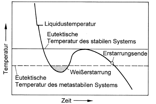
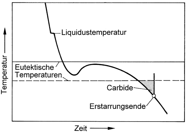
According to the iron-carbon phase diagram differentiation is made between stable Fe-C (iron graphite) and metastable Fe-Fe3C (iron cementite) system. In order to obtain gray or white solidification, depending on the purpose of use, the cast iron must be given the appropriate composition for the respective cooling rate specified for the casting process. Fundamentally, the aim is to influence the interval between the stable and the metastable eutecticequilibrium temperature (Figure 1).
Consequently, silicon is used for widening the interval and ensure gray solidification for the melt even with greater levels of supercooling. If, in contrast to that, white solidification is intended, the iron composition is selected such that the interval between the two eutectic temperatures is rather short.
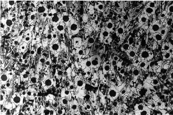
Moreover, the tendency towards gray or white solidification also depends on overheating of the melt (nucleation condition, s. Balance of nuclei) and the cooling rate, i.e. on wall thickness. The cooling curves illustrated in Figures 2, 4 and 6 emphasize this. With great cooling rates, the iron may cool down below the temperature of the metastable iron-cementite system so that the conditions are given for iron carbide (Fe3C) to develop; this particularly applies for thin cross sections and casting edges (referred to as edge hardness, chill due to carbide diffusion).If much heat is released during the eutectic reaction, the temperature of the residual melt may increase above the temperature of the meta-stable system again so that gray solidification is triggered (Fig. 2). The result is a mottled, whitish gray solidified structure as is illustrated in Fig. 3.
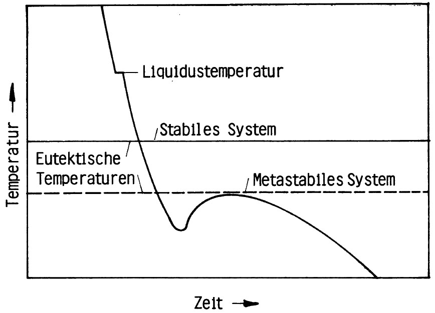
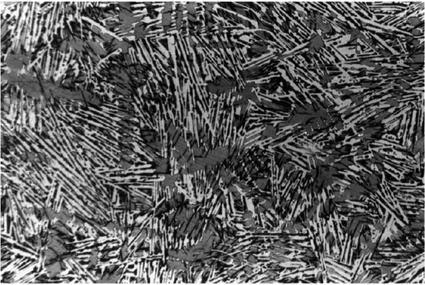
However, if white solidification below the eutectic temperature of the metastable system is maintained (Fig. 4), the structure of a typical white cast iron is obtained (Fig. 5).
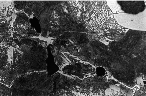
Carbides may also be formed at a later stage towards the end of the solidification process. As a general rule, the continuing eutecticsolidification releases enough heat to rise the temperature (recalescence); however, towards the end, the speed of reaction is reduced and temperatures begin to fall. In such a case it may occur for the residual melt to cool down to below the eutectic temperature of the metastable system, as is shown in Fig. 6, carbides may develop. They pile up along the boundaries of the previously grown eutectic grains (Fig. 7) and are referred to as grain boundary carbides.
Through inoculation, the number of nuclei for crystallization of the graphite eutectic is increased and thus the chill depth is reduced and grain refinement of the eutecticstructure is achieved, which in turn improves the strength properties in the casting.
Therefore, the material structure depends on the contents of carbon and silicon and on the respective inoculation effect. Moreover, eutectic disintegration of austenite to pearlite (in the metastable system) or to ferrite and graphite (in the stable system) must be taken into account.
In gray solidified cast iron the latter only takes place with very low cooling rates, so that normally pearlite is formed. This means that the eutectic condition of austenite during cooling of gray cast iron more or less quickly changes over to the metastable system; only in iron compositions with relatively high tendency to graphitization or with very low cooling rates (great wall-thicknesses) it is possible for ferrite to develop predominantly. Indeed, pearlitic structures are preferred in gray cast iron.
The critical factor for the strength of a type of cast iron, is the primary solidification structure, above all. The higher the proportion of primary austenitedendrite (s. Dendrites), the greater the strength. This is the main reason for the increase in strength with decreasing degree of saturation or carbon equivalent. Moreover, the graphite form plays a major role. The graphite particles weaken the structure and interrupt the continuity of the metal matrix.
The group of cast iron materials identified first is flake graphite cast iron (gray cast iron) with pearlitic or ferritic/pearlitic matrix and graphite lamellae of largely varying sizes. The tensile strength of this type of material is between 100 and 400 Mpa, however it provides almost no elongation at failure, at all; on the other hand it provides the great advantage of relatively low solidification rates of approx. 1 %. If development of the lamellar form is prevented and the carbon is rather available in nodule or spheroid form, the strength properties of the material are increased; but what is more, materials with significantly improved fracture toughness are obtained.
While production of melleable cast iron, in which elementary carbon is present in nodular to spheroidal form, represents a profoundly time-tested method, operational production of nodular graphite cast iron has only been in use for little more than five decades. The two materials last specified mainly differ in their respective silicon content, which is around 1 % in melleable cast iron and generally between 2 and 3 % in nodular graphite cast iron. Strength and toughness values roughly reach the same levels for both materials and are viable for great variation through alloying additives and heat treatment. In any case, they are far better than the property values of conventional flake graphite cast iron with otherwise comparable matrix.
Vermicular graphite originally developed as unwanted graphite form during production of nodular graphite cast iron upon insufficient or decaying treatment with nodularizing additives. Today, Compacted graphite iron is increasingly used in motor/engine construction. Due to its properties, this material can be classified between high-strength flake graphite cast iron (GJL) and nodular graphite cast iron (GJS). Good tensile strength of more than 400 MPa, elongation at failure of 2 to 6 %, excellent thermal conductivity and castability are characteristic properties of Compacted graphite iron (GJV).
The effect that the nodularizing elements have on crystal growth have been and still are the subject of numerous studies and analyses; and the structure formations of carbon have also been thoroughly evaluated. It is mainly due to application of state-of-the-art analysis processes (scanning electron microscope, electron probe micro analysis, etc.) that it was possible to successfully prove that all graphite forms are made up of hexagonal graphite plates with diameters of a few micrometers and a thickness of some tenth of micrometers and that the large number of graphite forms in cast iron for technical use only differ in terms of the arrangement of these plates.
While in gray cast iron graphite is diffused partly form the melt and partly during cooling, in melleable cast iron the decomposition of the iron carbide is only induced retroactively through special long-term annealing (Annealing for carbide decomposition). The graphite developed accumulates to form characteristic nodules and is referred to as temper carbon.
Differentiation is made between white (GJMW) and black (GJMB) melleable cast iron according to macroscopic appearance of the break surfaces.
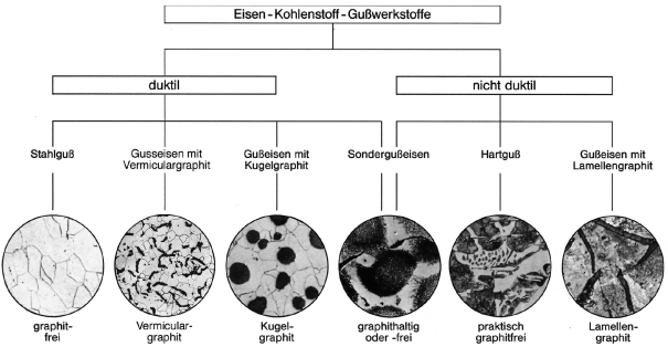
A general overview or iron-carbon casting materials is shown in Figure 8.
Additional references:
Metal matrix of cast iron
Structure formation of cast iron
Austenitic cast iron
Bainitic cast iron
Carbidic cast iron
Eutectic cast iron
Ferritic cast iron
Synthetic cast iron