Closing force regulator
Device for measuring and regulating the closing force in a die casting machine. The die locking force created with a toggle lever system (see Die locking) depends on the corresponding straight position, but the dead center position must not be reached. To prevent this, the locking force is measured and also regulated. The measurable quantity here is the tiebar stretch caused by the locking force.
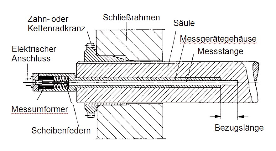
In addition to simple stretch measuring devices which are attached to the surface of the tiebars, there is also the possibility of using built-in mechanical or electric stretch measuring devices which are built in at the back end of the tiebar. A bore hole is made on the tiebar, into which a measuring device case is placed. This case concentrically surrounds a measuring rod which is plunged into a blind hold with a defined depth and is pressed into the bore hole by a Woodruff key (Figure 1). The measuring rod transfers the stretch in the blind hole area to a measurement transducer which determines the linear stretch in the area of the reference length and transforms it into an electrical signal. Changes in length in the area of 10µm can be recorded using this system. The electrical measurement, in addition to being highly accurate, has the advantage that the measurement values can be displayed directly in the dimension of the locking force. At the same time, the measurement values are also transformed into the electrical signals required for automatic correction of the locking force.
Another method for measuring the locking force is the determination of the hydraulic pressure required to stretch out the toggle lever hinges: here the measured value of the closing pressure is related to the effective locking force.
Automatic locking force regulation is carried out according to the measured tiebar stretches and the locking force. Unlike with the mold height adjustment, in which all four tiebar nuts are operated at the same time, to correct the locking force and achieve the same tiebar tension, it must be possible to adjust each of the four tiebar nuts individually. For this purpose, the drive for the mold height adjustment is uncoupled and each of the four tiebar nuts is set separately. For a mold height adjustment using a sprocket, this is done by disengaging a slide wheel on the affected tiebar nut from the sprocket. For drives using a worm screw, the connecting worm shaft is uncoupled. The drive itself is provided by a hydraulic motor with low power consumption.
The automatic regulation of the locking force is usually done with a step-by-step adjustment. Corrective steps are carried out until the chosen tolerance zone is reached. Devices of this kind usually work with the mold height adjustment and require the tiebar tensions to have already been corrected individually and compared with one another. It is therefore important to check the tiebar tension after fixing a die casting mold and, if necessary, to make the tiebar nuts the same by adjusting them individually.
If desired, most machines can be fitted with a device for the automatic control and correction of the tension in all four tiebars. By determining the limit values, a tolerance zone for the tiebar load can be set and if this is exceeded the automatic mold height adjustment is triggered. In this way, it is ensured that the optimum locking force is maintained and the fluctuations in the locking force which occur due to different thermal loads in the casting operation are compensated for automatically.