Pressurized water unit
Temperature controller for circulating pressurized water operation for automatic regulation of the operating temperature of a metal permanent mold (particularly die casting molds, see also Mold temperature and Thermal balance).Up to 90°C, water is more or less the only material used as a heat transfer medium in temperature controllers. Above 90 °C, the operator must decide whether to use water or heat transfer oil. The advantage of water is its high thermal capacity, i.e. the property which states how much heat energy a heat transfer medium is able to transport away. The thermal capacity of water is around twice as large as that of heat transfer oils. In addition, another advantage is the good heat transfer; the heat transfer coefficient between water and mold steel (s. Hot-forming steel) is around twice as high as that of heat transfer oil.
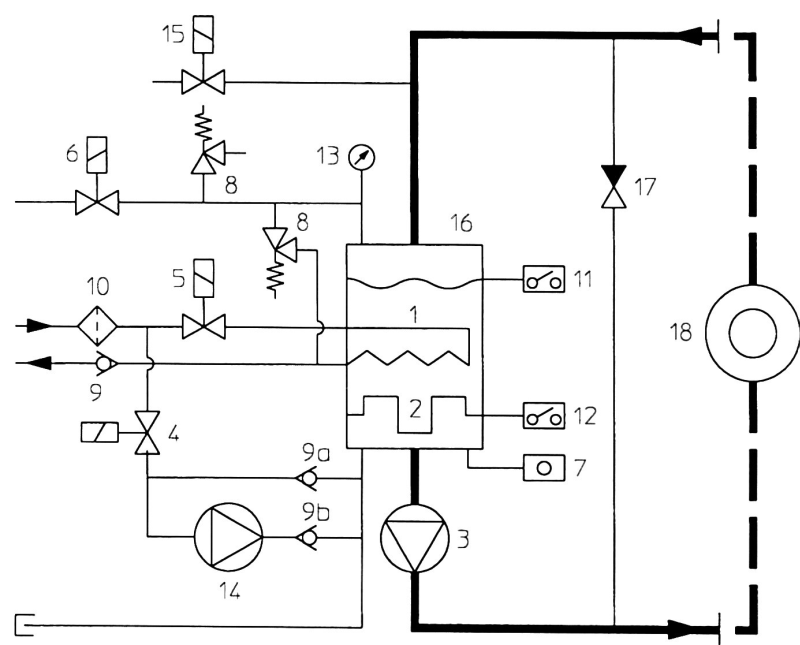
A further advantage of water is the low viscosity which, unlike that of heat transfer oil, remains more or less constant over the entire area of use. There is also the ecological advantage with regards to the handling and disposal as water, unlike oil, is easy to handle. For consumers with large amounts of heat transfer medium, the low expansion of water with increasing temperature is significant. For example: if 100ml of water is heated from 20°C to 140°Ct, the volume increases by approx. 7.4l; for oil, on the other hand, the increase is 10.4l. Therefore, a larger expansion tank is needed for oil units due to the larger increase in volume. As water is not carbonized, the construction of temperature controllers with higher specific heating powers is possible which means that they can be made smaller and therefore for a lower cost. Last but not least, water has the advantage that it is not flammable. In recent years, all of these advantages have lead to the use of water as a heat transfer medium and pressurized water units becoming more and more widespread.Pressurized water units can be used everywhere where the advantages of water plays a crucial roll, even above 90 °C. The principle is illustrated in Fig. 1 . In these units, the circulating water is under pressure, whereby the pressure is dependent on the flow temperature. The expansion from the water is collected in the expansion tank (16).
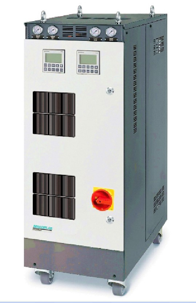
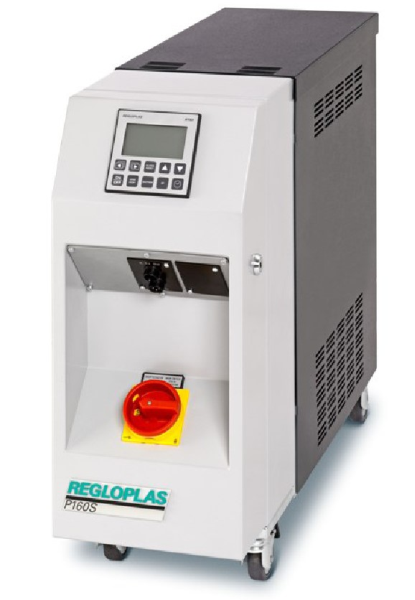
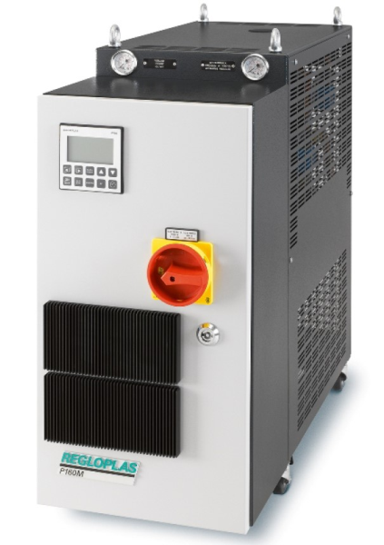
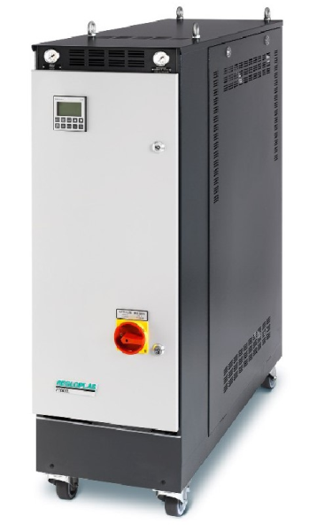
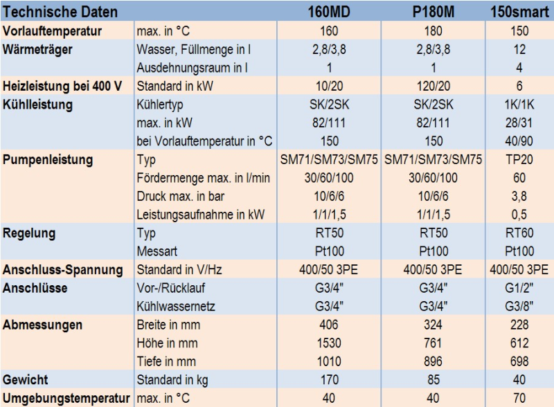
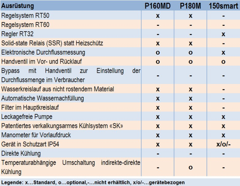
Due to the expansion of the water which is dependent on the temperature, the pressure in the unit and temperature control cycle rises. Starting at around 98°C, the water in the expansion tank begins to turn into steam until it reaches the saturation vapor pressure of the set flow temperature (e.g. 2.6 bar overpressure at 140°C). This means that the flow temperature is independent of the water supply pressure present. The way in which it works and the construction are described in the principle sketch in Figure 1 as follows: If the filling level is insufficient, the level control (11) opens the magnetic valve (4) and turns the filling pump (14) on. The filling pump makes it possible to refill even when the water supply pressure is smaller than the system pressure in the unit which is dependent on the flow temperature. The water then flows through the non-return valve (9a, 9b) into the system (16). In addition, for safety reasons, the unit also has the following elements: The non-return valve (9) prevents back flow of the water when the pressure in the cycle is higher than in the water supply. The safety valve (8) opens when the pressure in the cycle is too high. The manometer (13) shows the static system pressure which is made up of the saturated vapor pressure and the pressure caused by the water expansion. The magnetic valve (6) for the pressure relief is either opened automatically or controlled manually using a push button, depending on the design (after the water has previously been cooled to 80°C). This makes the temperature control cycle pressureless so that the unit can be separated from the consumer without any danger. When the unit is pressureless (magnetic valve 6 open), it is possible to empty the consumer by suction below 80°C. In addition, the magnetic valve (15) must be open in order to let air into the temperature control cycle. A leak-stop mode and emptying of the consumer through suction or blowing out is also possible. Pressurized water units with maximum flow temperatures of over 140°C are usually fitted with a filling pump (14) as refilling using the available water supply pressure is not always possible. Figures 2 to 5 (Regloplas AG) show the design of various pressurized water units. An overview of the technical data for selected pressurized water temperature control units is give in Table 1, the equipment which they have is listed in Table 2.
Additional references:
Oil temperature controller
Heating/cooling unit with bath heater