Cored wire process
Magnesium treatment method in which a steel hollow wire filled with magnesium granulate and/or with alloy elements such as silicon, Cer mixed metal, carbon, copper or nickel is used for the production of nodular graphite cast iron (see Magnesium treatment wire).
The wire is uncoiled into the liquid iron inside the treatment ladle by a special drive with adjustable feed rate. The method (first applied in 1989) has become well established; today, approx. 35% of all German foundries producing nodular graphite cast iron work with the cored wire process. The cored wire process has replaced the immersion method, the pressure chamber method, the osmosis method and partly also the pour-over method. The classification of Mg treatment wires is illustrated in Table 1 (ASK Chemicals Metallurgy GmbH).
The main influencing factors of the Mg wire treatment are:
- Sulfur content of the base iron
- Mg or filler range available
- Geometry of the treatment ladle
- Treatment temperature
- Treatment quantity
- Feeding rate/treatment time
- Geometry of the wire feed/setup of the treatment stand
As the aim of the Mg treatment is to obtain final sulfur values of 0.005 to 0.012%, each additional percentage point of sulfur prior the wire treatment means more wire, increased costs and more slag.
SA values of ≤ 0.080% should be achieved for cupolas and SA values of ≤ 0.015% for electric furnaces.
If the initial sulfur content is less than 0.010%, e.g. 0.008%, particular attention must be paid to inoculation. This may, for example, be the case upon pre-desulfurization. The sulfur values following magnesium treatment may then be in the region of 0.004%. The resulting iron is heavily deoxidized with very low oxygen and sulfur contents. It is “hard” and must be inoculated more strongly.
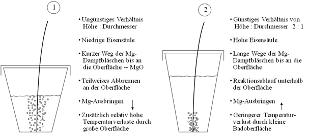
Slim ladles are particularly suitable as treatment ladles (height and diameter in a 2:1 ratio). The slim ladle allows for a high iron column, meaning that the Mg vapor bubbles have to travel long distances through the iron, therefore largely remaining in the iron (Fig. 1, ASK Chemicals Metallurgy GmbH) . In addition, temperature loss is low thanks to the relatively small surface area, and the formation of surface MgO is also low. Of decisive importance for all ladles is a minimum clearance of 300mm from the iron surface to the edge of the ladle.
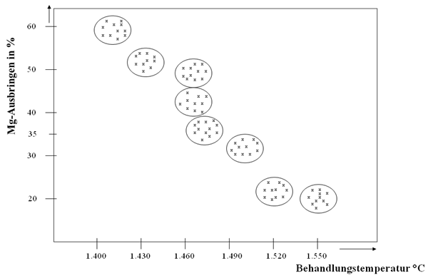
As with all treatment methods, there is a general dependency between the treatment temperature and magnesium yield in the Mg wire process, i.e. as the treatment temperature rises, the Mg yield falls and vice versa (Fig. 2, ASK Chemicals Metallurgy GmbH).
The treatment temperature is essentially determined by the pouring temperature. One advantage of the wire process compared to other Mg treatment methods is the fact that the temperature loss caused by the treatment (temperature measured prior to treatment to temperature measured immediately after treatment) is normally 30 to 50°C.
A minimum iron column of 500mm should always be aimed at with the treatment quantity. Up until now, 200kg has been the smallest unit treated with this iron column using appropriately slim ladles. In practice, the lowest treatment quantities are approx. 500kg. An upper limit cannot be specified directly, but treatment quantities of up to 30t are standard even today.
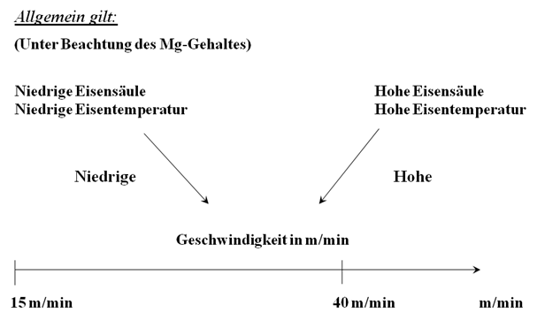
The feeding speed mainly depends on the height of the iron column and the iron temperature. It is normally between 15 and 40 m/min but can also be higher (Fig. 3, ASK Chemicals Metallurgy GmbH) . This results in treatment times of 0.5 to 2 min with quantities of 500 to 2,000kg and several minutes with larger iron quantities. For high iron quantities, a higher feeding rate may be applied. In addition, it is possible to use several machines in order to reduce feeding time.
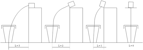
In many cases, the setup of the treatment stand is determined by the local conditions, the ladle sizes and the resources available. The treatment stand can be open, semi-encased or completely encased. In each case, it must be fitted with an adjustable extraction system. Fig. 4 (ASK Chemicals Metallurgy GmbH) shows schematic representations of various ways in which the feeding machine and treatment ladle can be arranged.
It is always important that the wire enters the iron with little or no bending. The wire should always enter the ladle bottom in its middle so that the reaction occurs just above the bottom. It is beneficial for the wire to be fed in a nearly or completely vertical manner.
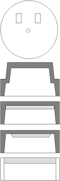
The cover required for the treatment ladle can have many different designs (Fig. 5, ASK Chemicals Metallurgy GmbH). It should be cast from nodular graphite cast iron due to the thermal requirements and lined with refractory material. The cover should have two holes for the extraction system in addition to the feeding tube for the wire.
Benefits of the wire process:
- The production of nodular graphite cast iron from a cupola furnace can be performed in a single treatment step.
- Lower material input and low treatment costs can be achieved.
- Temperature losses during treatment are low.
- It offers flexibility with regard to changing initial conditions such as sulfur content, temperature and treatment quantity. Despite varying initial sulfur contents and treatment temperatures, it is possible to achieve relatively constant Mg values.
- Secure documentation can be provided (PC control).
- The composition of the wire can be optimally adapted to account for metallurgical conditions.
- The introduction of the cored wire process for GJS production also offers an opportunity to produce compacted graphite iron with wire.