Interfering element
In cast iron, trace elements influence the graphite precipitation shape, the ferrite/pearlite ratio and the tendency towards metastable solidification. In particular with nodular graphite cast iron, a number of trace elements lead to degeneration of the spheroidal graphite formation which is why these elements are referred to as “interfering elements”. Such interferences were shown in the presence of lead, bismuth, antimony, tin, arsenic, aluminum, cadmium, silver, uranium, gallium, zinc, tellurium, thallium, selenium, boron, indium, phosphorus, sulfur, oxygen, titanium, vanadium, zircon, magnesium, cerium, lanthanum, yttrium and thorium. When present at higher concentrations, copper (especially in combination with any of the above elements), manganese and nickel also result in graphite degeneration.The technically relevant trace elements, such as lead, bismuth, zinc, antimony, titanium, arsenic and aluminum, are categorized into direct- and indirect-acting elements. However, an additional classification of the direct-acting elements into traces practically insoluble in iron and those slightly soluble in iron is also necessary.
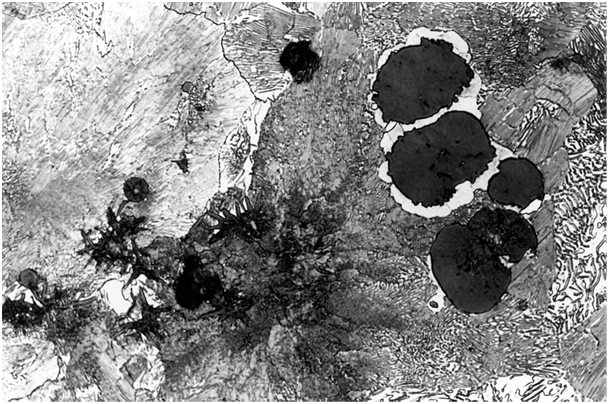
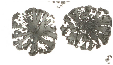
The group of trace elements nearly insoluble in iron mainly includes lead and bismuth. A noticeable interference effect on graphite formation can already be detected at a concentration of these elements in the range of 1.10-3%. The interference effect starts with the occurrence of vermicular graphite inclusions in the immediate vicinity of ideally structured spherulites (Fig. 1). Once a certain concentration limit (interference threshold) has been exceeded, a sudden drop in the degree of nodule formation occurs. The graphite then precipitates either in a lamellarpattern with split processes or as compact inclusions structured like temper carbon (Fig. 2). The secondary graphite can preferably be seen in a Widmanstätten pattern (Fig. 3).
The influence of the fraction of direct-acting interfering elements is low; however, the effects of lead and bismuth are additive. The interference threshold concentration is largely defined by the cooling rate (wall thickness, segregation).
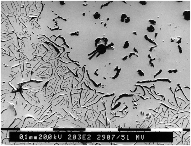
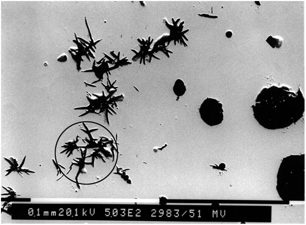
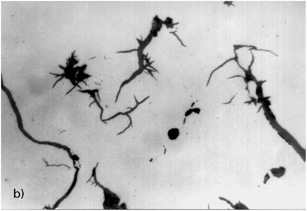
Direct-acting interfering elements having low solubility in austenite, which mainly includes antimony, zinc, arsenic, magnesium (and copper), progressively affect graphite formation as the level of interfering elements increases. The interference effects start with necking at the spherulite surface, proceeding to crab graphite, exploded graphite and spiky graphite at higher concentration (Figs. 4 to 6). The extent of the interference effect is not so much dependent on the cooling rate, but rather on the fraction of indirect-acting interfering elements. An additive effect of the elements in this group is probable.
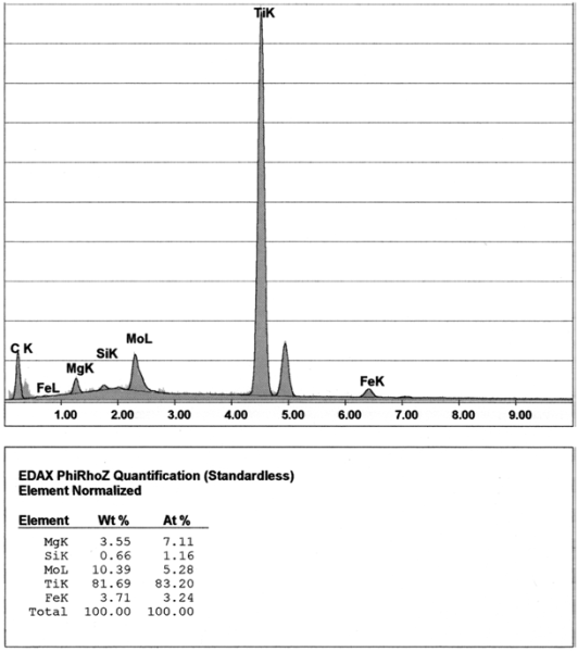
Only titanium can be definitely counted among the indirect-acting interfering elements. However, aluminum obviously also belongs to this group, even though this element also showed direct interferences. The degree of interference by titanium and aluminum is exceptionally dependent on the material’s trace element concentration and to a large extent on the cooling rate. The interference with graphite formation starts with increasing titanium and aluminum levels, being hardly detectable at first (partly, an improvement of graphite formation may even be seen). When certain concentrations are exceeded, titanium and aluminum result in a rapid drop in the degree of nodule formation, with the appearing graphite shapes (in particular flake graphite, partly in the vicinity of well-formed spherulites) being similar to interferences caused by lead and bismuth (Fig. 7).
With aluminum-silicon casting alloys, phosphorus acts as an interfering element in the eutectic and hypoeutectic range with respect to the formation of a fine-grained eutectic, and sodium and strontium have a refining effect, whereas this relation is reversed in the hypereutectic alloy range with sodium being considered as an interfering element and phosphorus as a grain-refining agent.